Difference between revisions of "Beta CSO"
| Line 7: | Line 7: | ||
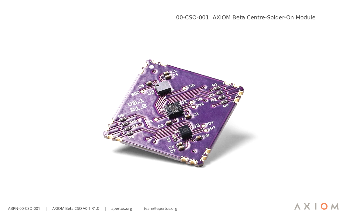
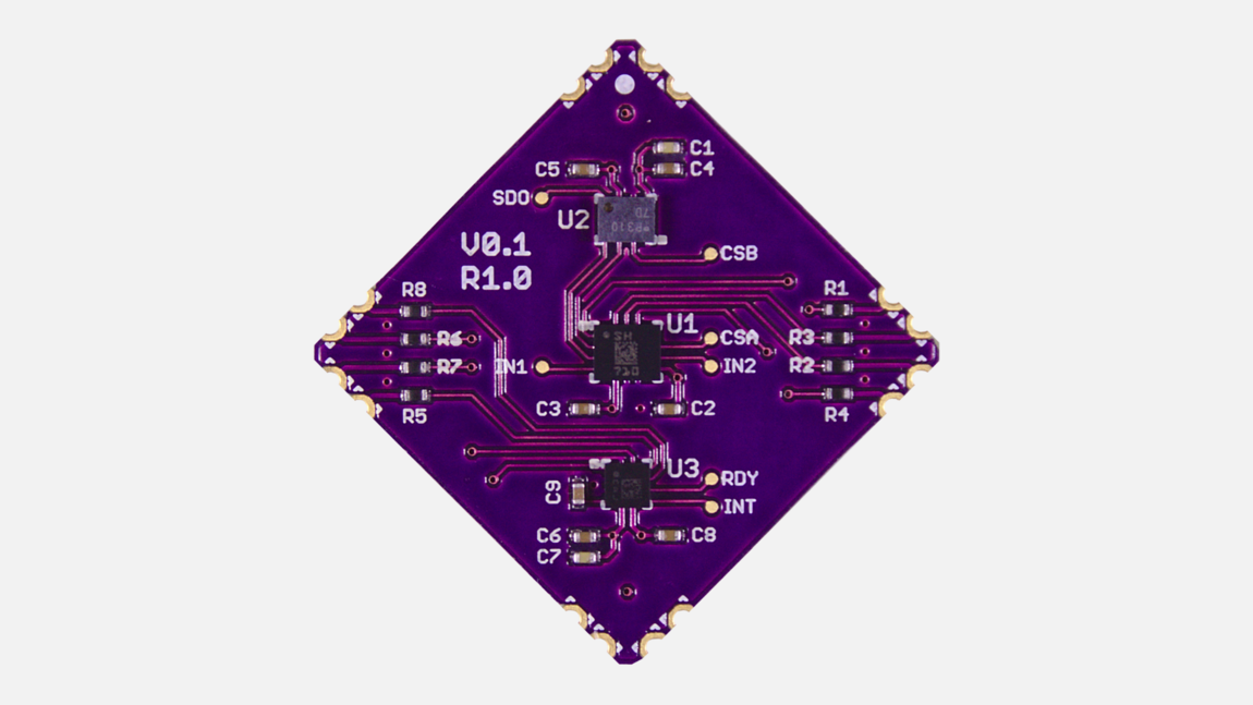
Some of the floor space in the centre of the AXIOM [[Beta Main Board]] has been left clear so that a CSO (centre-solder-on) board can be incorporated. This will host chips capable of measuring and controlling compensation processes via the camera's software, i.e. for orientation and acceleration (the same chips used to stabilise quadcopters and track movement in VR headsets), magnetic field related data, and three dimensional motion sensing. | Some of the floor space in the centre of the AXIOM [[Beta Main Board]] has been left clear so that a CSO (centre-solder-on) board can be incorporated. This will host chips capable of measuring and controlling compensation processes via the camera's software, i.e. for orientation and acceleration (the same chips used to stabilise quadcopters and track movement in VR headsets), magnetic field related data, and three dimensional motion sensing. | ||
Being situated directly behind the image sensor centre (see [https://wiki.apertus.org/index.php/AXIOM_Beta/Camera_Structure#AXIOM_Beta_PCB_Stack_Layout Camera Structure] means that these sensors are ideally positioned to supply data for image stabilisation or metadata about the camera’s orientation and movements during a shot. | Being situated directly behind the image sensor centre (see [https://wiki.apertus.org/index.php/AXIOM_Beta/Camera_Structure#AXIOM_Beta_PCB_Stack_Layout Camera Structure]) means that these sensors are ideally positioned to supply data for image stabilisation or metadata about the camera’s orientation and movements during a shot. | ||
Revision as of 09:43, 7 March 2019
Some of the floor space in the centre of the AXIOM Beta Main Board has been left clear so that a CSO (centre-solder-on) board can be incorporated. This will host chips capable of measuring and controlling compensation processes via the camera's software, i.e. for orientation and acceleration (the same chips used to stabilise quadcopters and track movement in VR headsets), magnetic field related data, and three dimensional motion sensing.
Being situated directly behind the image sensor centre (see Camera Structure) means that these sensors are ideally positioned to supply data for image stabilisation or metadata about the camera’s orientation and movements during a shot.
1 CSO1
The very first CSO simply had a few LEDs on it that could be made to blink in different patterns.
2 IMU CSO
The second design is intended as inertial measurement unit (IMU) and features 10 DOF (degrees of freedom) sensors: acceleration (3D), orientation (3D), magnetic field (3D) and air pressure (1) it also measure temperature, primarily for internal compensation.
Chips:
- LSM6DS3H: Accelerometer ODR up to 6.66 kHz, Gyroscope ODR up to 3.33 kHz, 2 - 5 €/pc.
- LIS3MDL: 3D Magnetometer ODR 20 Hz, 1 - 2 €/pc.
- DPS310: Air pressure and temperature sensor, ±0.05 m relative accuracy, 24 bit results, 1 - 3 €/pc.
3 Revisions
https://wiki.apertus.org/index.php/AXIOM_Beta_CSO_V0.01_R1.1

