Difference between revisions of "May 2022 CP Enclosure"
(→Parts) |
|||
| (8 intermediate revisions by the same user not shown) | |||
| Line 6: | Line 6: | ||
[[File:20190614_163841_HDR.jpg]] | [[File:20190614_163841_HDR.jpg]] | ||
[[File:Cp-asselby03-small.jpg]] | [[File:Cp-asselby03-small.jpg]] | ||
==Scope== | ==Scope== | ||
To | Most enclosure parts are to be CNC milled and anodized (black or clear) - the process is cost intensive but the results look and feel excellent. To reduce the overall cost we plan to produce some non-structural parts like connector plate covers as high quality SLA 3D print parts (no layers visible & smooth surfaces): | ||
[[File:Cp enclosure proposal 3d print parts 01.png]] | [[File:Cp enclosure proposal 3d print parts 01.png]] | ||
Note that existing AXIOM Beta hardware can be integrated into the CP enclosure if a THT sensor board is used. The ZIF sensor board does not fit as it has a bigger form factor with the larger socket and the lever. Also the THT sensor board has an opening underneath the image sensor and we attach a heat sink from the back, this is not possible with the ZIF sensor board. | Note that existing AXIOM Beta hardware can be integrated into the CP enclosure without any hardware modications if a [[Beta_CMV12K_THT_Sensor_Board|THT sensor board]] is used. The [[Beta_CMV12K_ZIF_Sensor_Board|ZIF sensor board]] does not fit as it has a bigger form factor with the larger socket and the lever. Also the THT sensor board has an opening underneath the image sensor and we attach a heat sink from the back, this is not possible with the ZIF sensor board. | ||
We currently produce Power Board V0.38 which features increased input range (6-17V) and a power button and fan interface. This allows running the Beta and the top fan (60x60x10mm fan integrated in CP enclosure) from a 12V supply (like a battery). Older Power Board versions were 5V input only, there are also 5V fans but the selection is more limited. Note that we do not have a finished power button PCB but the interface to connect it in the future is there. | |||
==Early adopter goals== | ==Early adopter goals== | ||
| Line 19: | Line 22: | ||
* testing of internal fan, air circulation, temperature monitoring, fan control in software | * testing of internal fan, air circulation, temperature monitoring, fan control in software | ||
* starting efforts to design print labels on the enclosure (logo, instructions, connectors, etc.) | * starting efforts to design print labels on the enclosure (logo, instructions, connectors, etc.) | ||
==Parts== | ==Parts== | ||
parts are prepared for production here: | |||
https://cloud.apertus.org/index.php/s/WCE3Z5G5wxQLMYA | https://cloud.apertus.org/index.php/s/WCE3Z5G5wxQLMYA | ||
==Notes== | |||
* 6-14V input supply range over X2 header on Power Board (software still needs to be written) - requires cable to barrel jack in cap bottom. | |||
Latest revision as of 12:45, 8 January 2023
We started collecting people interested in becoming AXIOM Beta Compact (CP) enclosure early adopters on May 1st. If you are interested please contact us: https://www.apertus.org/contact
The idea is that we optimally gather a group of 10+ people to benefit from the manufacturing prices getting lower with raising quantities.
Once we have a headcount we will be able to deliver an accurate estimate for the cost.
1 Scope
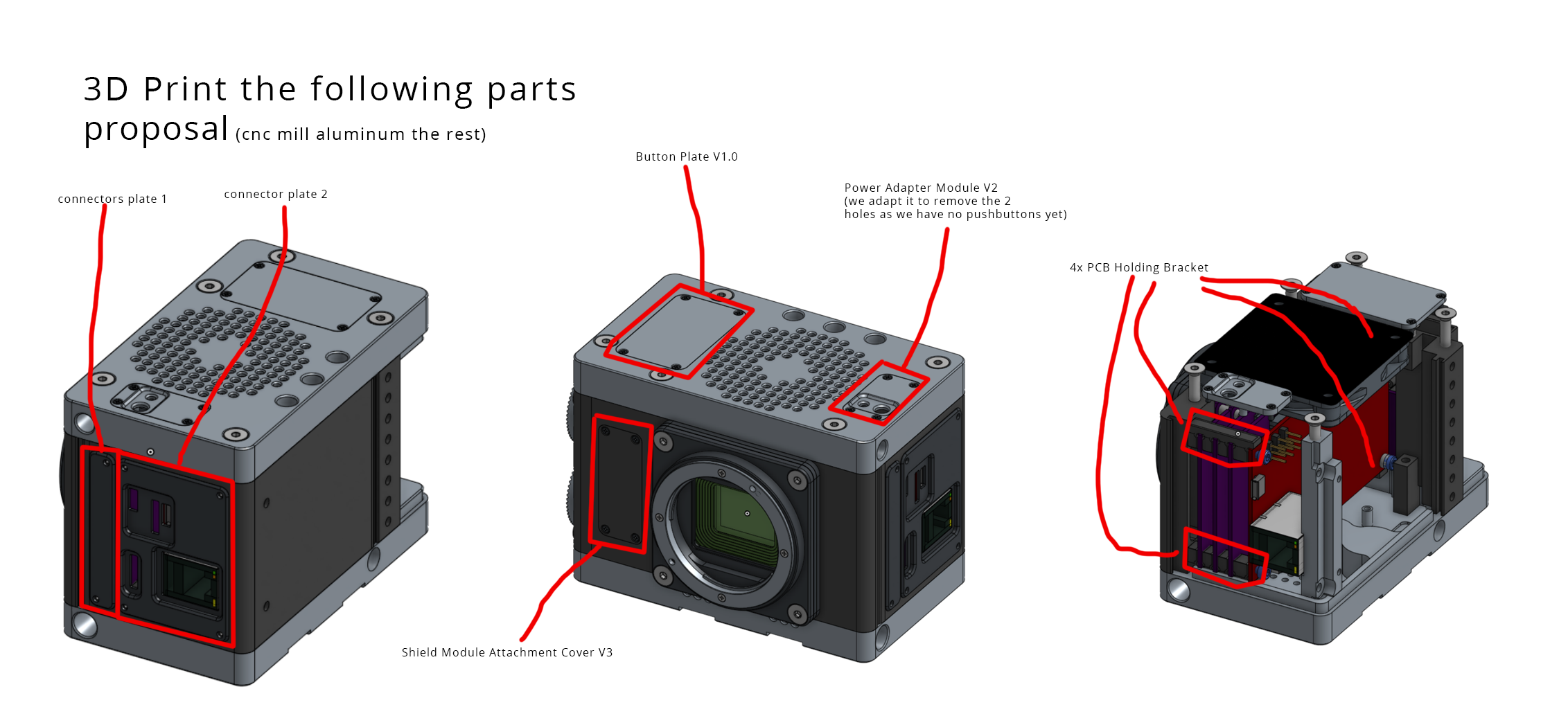
Most enclosure parts are to be CNC milled and anodized (black or clear) - the process is cost intensive but the results look and feel excellent. To reduce the overall cost we plan to produce some non-structural parts like connector plate covers as high quality SLA 3D print parts (no layers visible & smooth surfaces):

Note that existing AXIOM Beta hardware can be integrated into the CP enclosure without any hardware modications if a THT sensor board is used. The ZIF sensor board does not fit as it has a bigger form factor with the larger socket and the lever. Also the THT sensor board has an opening underneath the image sensor and we attach a heat sink from the back, this is not possible with the ZIF sensor board.
We currently produce Power Board V0.38 which features increased input range (6-17V) and a power button and fan interface. This allows running the Beta and the top fan (60x60x10mm fan integrated in CP enclosure) from a 12V supply (like a battery). Older Power Board versions were 5V input only, there are also 5V fans but the selection is more limited. Note that we do not have a finished power button PCB but the interface to connect it in the future is there.
2 Early adopter goals
- collect general feedback about ergonomics, handling, look & feel
- testing of internal fan, air circulation, temperature monitoring, fan control in software
- starting efforts to design print labels on the enclosure (logo, instructions, connectors, etc.)
3 Parts
parts are prepared for production here:
https://cloud.apertus.org/index.php/s/WCE3Z5G5wxQLMYA
4 Notes
- 6-14V input supply range over X2 header on Power Board (software still needs to be written) - requires cable to barrel jack in cap bottom.

