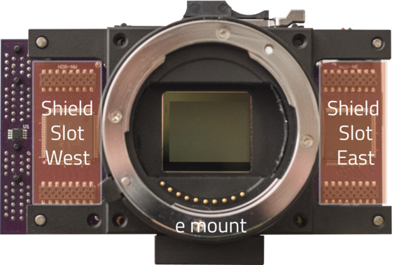
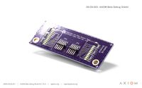
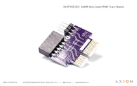
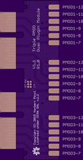
Difference between revisions of "AXIOM Beta/Manual"
| (240 intermediate revisions by 9 users not shown) | |||
| Line 1: | Line 1: | ||
'''Preamble''' | '''Preamble''' | ||
* For | * For all resources related to the camera see [[AXIOM Beta|AXIOM Beta Main Page]]. | ||
* For an introduction to the camera's components see AXIOM Beta [ | * To see how community members are using the camera see [[AXIOM Beta/Case Studies | Case Studies]]. | ||
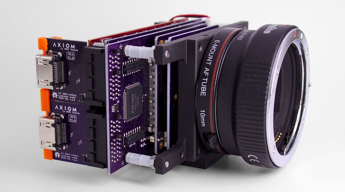
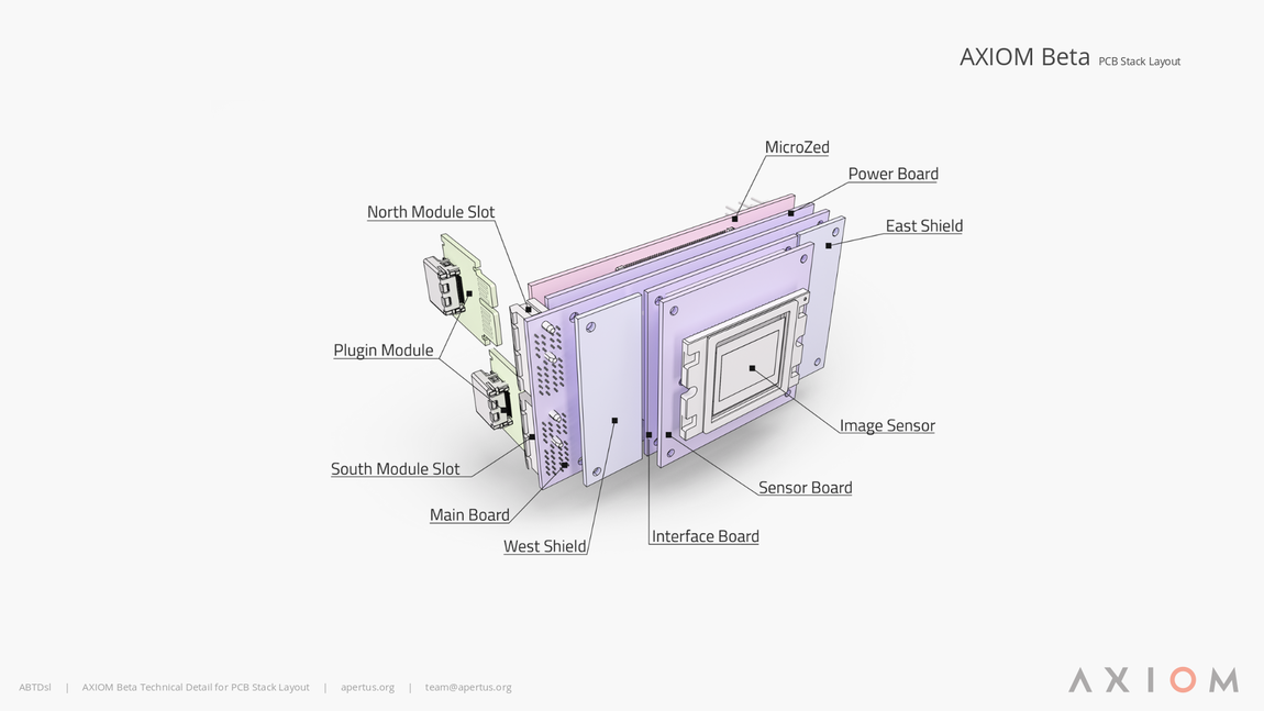
* For an introduction to the camera's components see AXIOM Beta [[AXIOM_Beta/Camera_Structure | Camera Structure]]. | |||
* For sample still/video files, camera availability, socials and other important stuff see [[Useful Links]]. | * For sample still/video files, camera availability, socials and other important stuff see [[Useful Links]]. | ||
---- | ---- | ||
Should you experience difficulties or have a query and require live assistance please come to our IRC channel and see if a community member is currently around for live chat: https://www.apertus.org/irc-chat | |||
Otherwise please email us through the [https://www.apertus.org/contact contact details]. | |||
To use this manual a deep technical understanding of the AXIOM is not required. You need to use Linux though and it helps if you have used a commandline before. | |||
---- | ---- | ||
__TOC__ | |||
=General Information= | |||
= | ==Safety Precautions== | ||
This device and its software is provided without warranty of Merchantability or | |||
fitness for any particular purpose. apertus° assumes no responsibility or | |||
liability for any loss or damage as a result of the use or misuse. USE AT YOUR | |||
OWN RISK. You have root access to this system and can potentially brick and | |||
damage the hardware from the command line interface - be responsible and when in | |||
doubt consult with apertus° before doing anything potentially harmful to your | |||
camera. | |||
Our hardware is not weather sealed so use extra caution when operating the equipment outdoors. In particular sea/salt water spray is very harmful to electronics. | |||
| Line 45: | Line 39: | ||
[[File:Side-02.jpg | 500px]] | [[File:Side-02.jpg | 500px]] | ||
[[File: | [[File:AXIOM-Beta-Developer-Kit-Shields 1.png|500px]] | ||
= | =Operating Basics= | ||
==Prepare Your AXIOM Beta Camera for Use== | |||
0. Flash the firmware → [[AXIOM_Beta_Firmware_Version_2.0]] | |||
---- | # We started shipping AXIOM Beta Developer Kits with Wi-Fi USB sticks. This allows you to connect your device to the Wi-Fi access point of the camera after it booted to get SSH access or open the web interface in your browser without having to deal with cables and IP address setups on your router. | ||
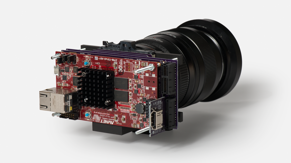
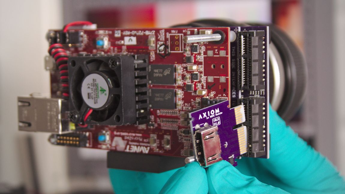
# Alternatively: Use a micro-USB cable to connect the camera's MicroZed development board (USB UART) to a computer. The MicroZed board is the rearmost, red PCB (There is another micro-USB socket on the Power Board, but that is the JTAG Interface). | |||
# Alternatively: Connect the Ethernet port on the MicroZed to an Ethernet port on your computer. You might have to use an Ethernet adapter on newer, smaller machines which often come without a native Ethernet port. | |||
# Connect the AC adapter to the camera's Power Board. (to power the camera off at a later point, you need not disconnect the adapter from the board but can just unplug the cord from the adapter.) | |||
Each camera ships with an external AC power supply that provides 5V and 6-8A. | |||
The Beta requires two 5V inputs (one for the Microzed, one for the rest of the hardware). Each 5V supply should be able to provide at least 2-3A. The total power consumption in normal operation was measured to be around 10W. During boot up there are spikes of higher power consumption. | |||
== | ===LED Indicators=== | ||
Once the AXIOM is powered on, you should see a green LED permanentely ON and a red LED with a heart-beat pattern. | |||
# the green LED is directly connected to the MicroZed Power | |||
# the red LED is controlled by the PS (Linux) | |||
# the blue LED ([[AXIOM_Beta/Manual#Initiate_the_Image_Sensor|see below]]) flashes with every triggered image acquisition. | |||
NOTE : If the red LED is permanently ON or not there, chances are good that the SD card is bad/missing and the MicroZed does not boot. | |||
| Line 63: | Line 67: | ||
[[File: | [[File:Command prompt.png | 200px| thumb | 200px]] | ||
==Prepare Your | ==Prepare Your Computer for Use With Your Camera== | ||
To communicate with your AXIOM Beta camera you will send it instructions via your computer's command line. | |||
In case you have not worked with a shell (console, terminal) much or ever before, we have prepared detailed instructions to help you get you set up. The steps which need to be taken to prepare your machine sometimes differ between operating systems, so pick the ones that best apply to you(r system). | |||
'''Note:''' Dollar signs <code>$</code> placed in front of commands are not meant to be typed in, they denote the command line prompt (a signal indicating the computer is ready for user input). It is used in documentation to differentiate between commands and the output resulting from commands. The prompt might look different on your machine (e.g. an angled bracket <code>></code>) and be preceded by your user name, computer name or the name of the directory that you are currently inside. | |||
===WiFi Access Point Setup=== | |||
[[File:Beta-wifi.jpg]] | |||
Connecting a USB wifi dongle (that supports Soft-AP) to the AXIOM Beta USB port allows controlling the camera via wireless connection on Firmware 2.0. | |||
The following devices have been tested so far: | |||
{| class="wikitable" | |||
! Device | |||
! Wifi Chip | |||
! Cost | |||
! Comment | |||
---- | |- | ||
| Think Penguin TPE-N150USB | |||
| Atheros AR9271 | |||
| 54$ | |||
| works out of the box with FW2.0 | |||
|- | |||
| Technoethical TET-N150 | |||
| Atheros AR9271 | |||
| 50€ | |||
| works out of the box with FW2.0 | |||
|- | |||
| Edimax EW-7811UN | |||
| Realtek RTL8188CUS | |||
| 8€ | |||
| works out of the box with FW2.0, connection speed is very slow, | |||
alternative rlt8xxxu driver does not support AP mode | |||
|- | |||
| TB® | |||
| Ralink 5370 | |||
| 9€ | |||
| works out of the box with FW2.0 | |||
|- | |||
| Logilink WL0145A | |||
| Realtek RTL8188EUS | |||
| | |||
| does not work | |||
|- | |||
| tp-link TL-WN725N | |||
| Realtek RTL8188EUS | |||
| | |||
| does not work | |||
|- | |||
| Dootoper AC1200 | |||
| RTL88x2bu AC1200 | |||
| | |||
| does not work | |||
|- | |||
| tp-link Archer T2U nano | |||
| RTL8811AU | |||
| | |||
| does not work | |||
|- | |||
| EDUP AC1200 | |||
| RTL88x2bu AC1200 | |||
| | |||
| does not work | |||
|- | |||
| MECO ELEVERDE WiFi Adapter | |||
| Realtek RTL8188GU | |||
| | |||
| does not work | |||
|- | |||
| Agedate WLAN Adapter | |||
| RTL88x2bu AC1200 | |||
| | |||
| does not work | |||
|- | |||
| Logilink WL0084E | |||
| | |||
| | |||
| does not work | |||
|- | |||
| TP-Link UB400 Nano | |||
| | |||
| | |||
| does not work | |||
|} | |||
In a recent Firmware 2.0 the wifi accesspoint setup is already preconfigured and will start automatically after the AXIOM Beta has booted. This means the AXIOM Beta itself will become an access point you can connect to. The default SSID (wireless network's name) is called "axiom". | |||
Once connected the DNS entry for your camera is configured as "axiom.camera". | |||
This means you can ssh to the camera like this: | |||
Limited User: | |||
ssh operator@axiom.camera | |||
Administrative User: | |||
ssh root@axiom.camera | |||
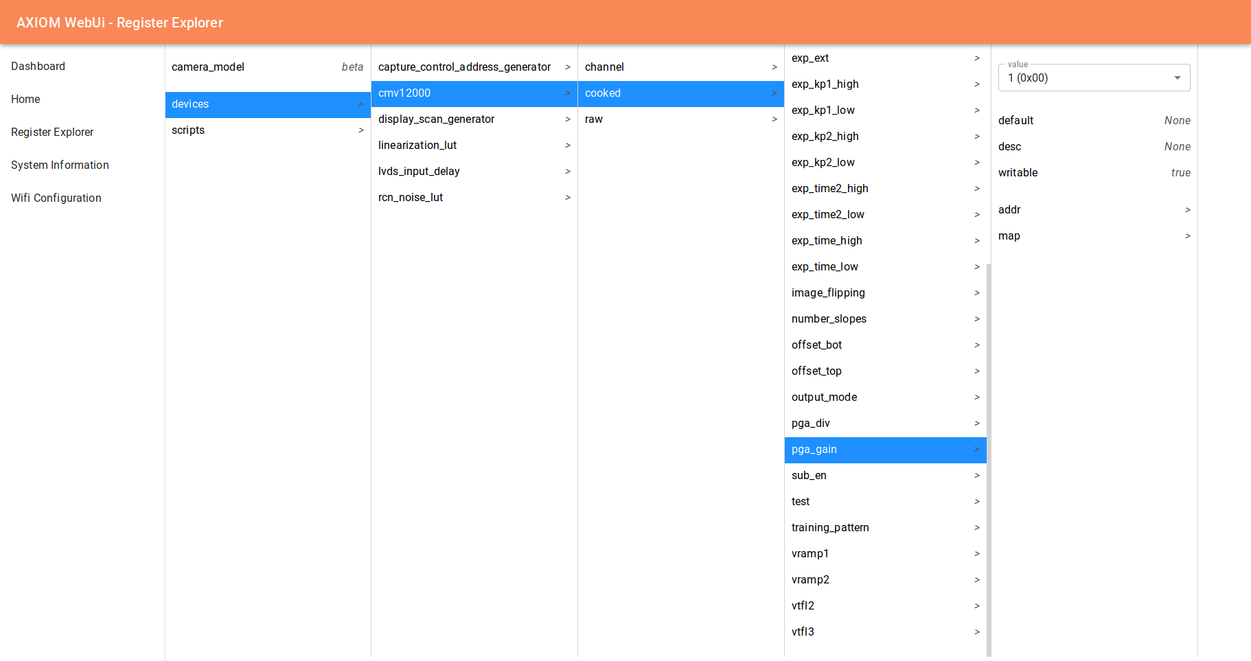
Or you can open the web user interface running on the camera by opening '''axiom.camera''' in your browser. | |||
[[File:Register explorer screenshot.png]] | |||
Note that some operating systems will complain about not having internet connectivity after connecting to the axiom hotspot and might automatically switch to your home/office WIFI access point again to provide you with internet connectivity. | |||
====Connecting the AXIOM Beta to another Wifi Access Point==== | |||
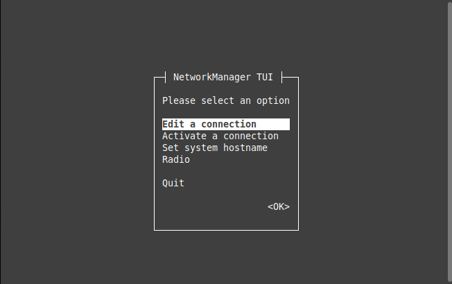
The wireless adapter cannot only create an access point you can also connect the AXIOM Beta to an existing access point. To do this the tool ''nmtui'' is preinstalled in the cameras firmware. | |||
''nmtui'' can be started via serial console for example and the first "page" looks like this: | |||
[[File:Nmtui01.jpg]] | |||
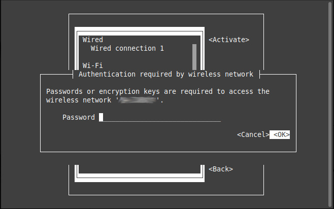
You can then activate a connection, choose an existing Wifi SSID and enter the password to connect: | |||
[[File:Nmtui02.jpg]] | |||
''ifconfig'' can be used afterwards to check if the AXIOM Beta received an IP successfully from the connected wifi network. The AXIOM Beta will remember the passwords to networks you connected successfully and connect to them automatically on the next boot. | |||
====WiFi Access Point Setup Details==== | |||
If you want to dive deeper: | |||
Check your wifi card: | |||
ifconfig | |||
Turn on wifi card: | |||
ifconfig wlan0 up | |||
Search wifi essid/hotspot name: | |||
iwlist wlan0 scan | |||
Setting up Essid and password: | |||
WEP | |||
iwconfig wlan0 essid "yourhotspotname" key yourpassword | |||
ASCII | |||
iwconfig wlan0 essid "yourhotspotname" key s:asciikey | |||
WPA2 (tested and working) | |||
update mirrors database (it is required to connect to the Internet via Ethernet): | |||
pacman -Syy | |||
install wpa_supplicant: | |||
pacman -S wpa_supplicant | |||
Configuration with wpa_passphrase - https://wiki.archlinux.org/index.php/WPA_supplicant | |||
create basic configuration file | |||
MYSSID = name of your wireless network | |||
passphrase = password to connect to your wireless network | |||
wpa_passphrase MYSSID passphrase > /etc/wpa_supplicant/example.conf | |||
ip link set dev wlan0 up | |||
wpa_supplicant -B -i wlan0 -c /etc/wpa_supplicant/example.conf | |||
if nl80211 driver does not support the given hardware. The deprecated wext driver might still support the device: | |||
wpa_supplicant -B -i wlan0 -D wext -c /etc/wpa_supplicant/example.conf | |||
dhcpcd wlan0 | |||
Autostart connect https://wiki.archlinux.org/index.php/netctl | |||
copy config from example: | |||
cp /etc/netctl/example/wireless-wpa /etc/netctl/wireless-wpa | |||
edit the config for you network (interface/ESSID/key): | |||
nano /etc/netctl/wireless-wpa | |||
First manually check that the profile can be started successfully with: | |||
netctl start wireless-wpa | |||
If the above command results in a failure, then use | |||
journalctl -xn | |||
netctl status profile | |||
to obtain a more in depth explanation of the failure. (profile might already been started) | |||
- | Enable: | ||
netctl enable wireless-wpa | |||
This will create and enable a systemd service that will start when the computer boots. Changes to the profile file will not propagate to the service file automatically. After such changes, it is necessary to reenable the profile: | |||
netctl reenable wireless-wpa | |||
=== | ===USB to UART Drivers=== | ||
For the USB connection to work, you will need drivers for bridging USB to UART (USB to serial). Under Linux this works out of the box in most distributions, for other operating systems they can be [https://www.silabs.com/products/development-tools/software/usb-to-uart-bridge-vcp-drivers downloaded] from e.g. Silicon Labs' website – pick the software provided for your OS and install it. | |||
===Serial Console=== | |||
The tool we recommend for connecting to the AXIOM Beta camera via serial port with Mac OS X or Linux is [http://linux.die.net/man/1/minicom minicom]; for connections from Windows machines, we have used [http://www.putty.org Putty]. | |||
====Linux Setup==== | |||
Check if you already have minicom installed on your system by trying to run it: | |||
$ minicom | |||
Your system will respond with a message like <code>bash: command not found: minicom</code> if it's not installed. | |||
'''Install minicom''' | |||
' | Install the minicom package like you'd install other software on your system – which could be via a GUI tool or using <code>aptitude</code> or <code>apt-get</code> (for wich you might need super-user rights), e.g.: | ||
$ apt-get install minicom | |||
or | |||
$ sudo apt-get install minicom | |||
====Mac OS X Setup==== | |||
< | You will want to have [http://brew.sh/ Homebrew] installed on your system to use <code>minicom</code> for serial communication as it's more convenient than using <code>screen</code>. | ||
which | '''Note:''' Homebrew is a package manager for Mac - a piece of software that helps you install other software on your Mac machine, particularly software which is readily available on Linux but which does not come in the form of Mac "applications" which you can download via your web browser and simply drop into your Applications folder. | ||
Open Terminal.app (or your preferred terminal emulator if you have another installed). Terminal can be found via e.g. Spotlight search or via the Finder menu: <code>Go > Utilities > Terminal.app</code>. | |||
Check if you already have brew installed by entering the brew command: | |||
$ brew | |||
If you don't have Homebrew installed, your shell will reply with something like <code>bash: command not found: brew</code>. Otherwise, it will spit out a list of <code>brew</code> commands. | |||
'''Installing Homebrew''' | |||
To install Homebrew, go to the [http://brew.sh/ Homebrew] website and follow the install instructions there. You can simply copy the command used for installing Homebrew from their website and then paste it into your terminal. | |||
'''Installing minicom''' | |||
With brew installed, you want to install minicom: | |||
$ brew install minicom | |||
Homebrew will tell you if you already have minicom installed on your system (e.g. <code>Warning: minicom-2.7 already installed</code>), otherwise it will install it for you. | |||
====minicom Configuration==== | |||
Once you have minicom installed, you need to configure it in order to talk to the camera. You can either use the configuration file we prepared or configure it yourself, following these step-by-step instructions. | |||
'''Linux''' | |||
Go to the minicom setup page: | |||
<pre>$ minicom -s</pre> | |||
In the "Serial port setup" subpage, check that "Serial Device" 's name is the good one (usually /dev/ttyUSB0 on Linux) and check the baud rate (115200). | |||
'''Mac''' | |||
Download [[Media:Minirc.USB0_Mac.zip|the settings file for Mac]], unzip it and place it in the <code>etc</code> directory of your minicom install. | |||
The minicom installation can be found in the standard directory used by homebrew, <code>/usr/local/Cellar</code>, in a subdirectory based on the minicom version number, e.g. <code>/usr/local/Cellar/minicom/2.7/etc | |||
</code>. | |||
You can also use Homebrew's <code>info</code> command to find minicom on your hard disk: | |||
<pre>$ brew info minicom</pre> | |||
which will output general information on the installed package, including its install directory e.g.: | |||
<pre> | |||
minicom: stable 2.7 (bottled) | |||
Menu-driven communications program | |||
https://alioth.debian.org/projects/minicom/ | |||
/usr/local/Cellar/minicom/2.7 (17 files, 346.6K) * | |||
Poured from bottle on ...</pre> | |||
===Serial Connection via USB=== | |||
While the AXIOM Beta can be connected to via USB UART (USB to serial), a serial connection is not the preferred way to communicate with the camera but rather in place for monitoring purposes. | |||
However, a serial connection is needed to set up communication via ethernet/LAN (the better suited way to talk to the camera): as the Beta only allows for secure ethernet connections, you will have to connect to the camera via serial port first and copy over your SSH key. | |||
Below are two different methods for connecting to the AXIOM Beta camera, using a program called minicom and an alternative program called screen. We suggest you try them in the order below, so if you can connect with minicom great, if not try screen. | |||
==== Connect Using minicom ==== | |||
'''Note:''' You will not be able to use the terminal window you initiate the serial connection in for anything else (it needs to remain open while you access the camera), so it might make sense to open a separate window solely for this purpose. | |||
---- | With minicom installed and properly [https://github.com/apertus-open-source-cinema/beta-documentation/tree/master/AXIOM%20Beta configured], all you need to do is run the following command to start it with the correct settings: | ||
<pre>$ minicom -8 USB0</pre> | |||
On successful connection, you will be prompted to enter user credentials (which are needed to log into the camera). | |||
If your terminal remains blank except for the minicom welcome screen/information about your connection settings, try pressing enter. If this still does not result in the prompt for user credentials – while testing, we discovered the ''initial'' connection with minicom does not always work – disconnect the camera from the power adapter, then reconnect it: in your minicom window you should now see the camera's operating system booting up, followed by the login prompt. (From then on, connecting with minicom should work smoothly and at most require you to press enter to make the login prompt appear.) | |||
The default credentials Firmware 1.0 are: | |||
<pre>user: root | |||
password: beta</pre> | |||
The default credentials Firmware 2.0 are: | |||
<pre>user: operator | |||
password: axiom</pre> | |||
<pre>user: root | |||
password: axiom</pre> | |||
'''Alternatives''' | |||
Before you can use any tool to initiate a serial connection with your Beta camera you need to know through which special device file it can be accessed. | |||
Once the Beta is connected and powered on (and you installed the necessary drivers), it gets listed as a USB device in the <code>/dev</code> directory of your file system, e.g.<br> | |||
<code>/dev/ttyUSB0</code> (on Linux)<br>or<br> | |||
<code>/dev/cu.SLAB_USBtoUART</code><br> | |||
<code>/dev/tty.SLAB_USBtoUART</code> (on Mac). | |||
You can use a command such as: | |||
<pre>$ ls -al /dev | grep -i usb</pre> | |||
to list all USB devices currently connected to your machine. | |||
==== Connect Using screen ==== | |||
To connect to the camera, use the command: | |||
<pre>$ screen file_path 115200</pre> | |||
where <code>file_path</code> is the full path to the special device file (e.g. <code>/dev/ttyUSB0</code> or <code>/dev/cu.SLAB_USBtoUART</code>). | |||
You might have to run the command with superuser rights, i.e.: | |||
<pre>$ sudo screen file_path 115200</pre> | |||
On successful connection, you will be prompted to enter user credentials needed for logging into the camera.<br> | |||
If your terminal remains blank, try pressing enter. | |||
The default credentials Firmware 1.0 are: | |||
<pre>user: root | |||
password: beta</pre> | |||
The default credentials Firmware 2.0 are: | |||
<pre>user: operator | |||
password: axiom</pre> | |||
<pre>$ | ====Disconnect==== | ||
To exit the camera's operating system, use: | |||
<pre>$ exit</pre> | |||
The result will be a logout message followed by a new login prompt. | |||
< | To suspend or quit your <code>screen</code> session (and return to your regular terminal window) use one of the following commands: | ||
<pre>CTRL+a CTRL+z</pre> | |||
<pre>CTRL+a CTRL+\</pre> | |||
===Ethernet Connection Using SSH=== | |||
To access the AXIOM Beta via Ethernet – which is the preferred way to communicate with it and will also work remotely, from a machine which is not directly connected to the camera – authentication via SSH is required. | |||
====SSH Keys How-to For Linux and Mac==== | |||
If you have never created SSH keys before or need a refresher in order to create a new pair, see the How-to below. | |||
=====Storage Location / Find Existing Keys===== | |||
'''Mac & Linux''' | |||
< | By default, the ssh directory is located at <code>~/.ssh</code>, and contains key files called <code>id_rsa</code> and <code>id_rsa.pub</code>, respectively. Check if the directory exists and already contains keys by listing its contents: | ||
<pre>$ ls -al ~/.ssh</pre> | |||
---- | If the directory doesn't exist or is empty and you don't have your SSH keys stored elsewhere on your machine, follow the instructions for key creation | ||
below. | |||
=====SSH Key Creation===== | |||
Linux machines as well as new Macs usually come pre-installed with the tools you need for creating SSH keys. To start the key creation process, use the command: | |||
<pre>$ ssh-keygen -t rsa -b 4096 -C "yourname@yourmachine"</pre> | |||
Note: The <code>-C</code> argument is used to add a comment which can help indentify your key as yours/your machine's, which might come in handy once you use other computers to connect to your Beta camera. If you leave it out, your default username/hostname will be used (you can check with <code>$ echo "$(whoami)@$(hostname)"</code> either beforehand or in another Terminal window to find out what it is), though you can always change the comment part again later on. | |||
<br> | |||
You will be prompted for a file in which to save the keys. To use the default install location (recommended), just press Enter. | |||
Next, you will be asked to enter a passphrase. Using a passphrase means greater security, though you can continue without one by just pressing Enter. In either case you will be asked to confirm your passphrase (by re-entering it if you used one, or pressing Enter again in case you did not). | |||
Subsequently, your keys will be created and saved in the directory you specified (<code>~/.ssh</code> by default). You can have your machine print out your public key for you by using the command: | |||
<pre>$ cat ~/.ssh/id_rsa.pub</pre> | |||
The output will look approximately like this: | |||
<pre class="code">ssh-rsa AAAAB3NzaC1yc2EAAAADAQABAAACAQCj8ZHA1ehuCwXvEzyG20Cv0SX1BZ9uyXvON4mDOJJHtG7WolOZG0QPYEPpNxUIFuuvYYl/ffNrV9v2cXyit28N28kqHprGlQK43r9poLACIU4BA6uFIFp5++tEsAiM0bCbQlExcZvxvQQONY8Slrl9/2kbEwFSnYdY9ORQxYsxB0gHAaDq8KFj6XQXZlyrLC46uoUDvF9DJOYmRBV/6gieWfPo3jaLS6S7mLICSB3jUK81ZD5D7IJrh1kifahmSyaui1kU4PxmmqdwPG8sFGhTsZTCavngYNzNaK1XhTeUppHblDuQUc6Z02K62Od6LMgk7khdrFlBrzpt5Yds3CztTiJ1PI1XKawhRLEMJe4ekXg+i+bz8vmuMiOrnzrK4U/GCs2a7pjx2mC4WBDd7xJKwYh9HMmLAT9l0VKH+BwEBJXq/0EqKDvMwpUn1h3HQey+Rcujf77IX+eSafyg762OKTRAniCSuhiH2jUWEzhj7cjTRIllxwXOBUUS6FtUYBUQ/sBE3bMmY85VMyF+6z6iiep7VZ9vBMNJtuol2k1wKsrrD3Finynr8gPqO2ghjK+ZvkxjgYANvV+gSvWVo2R8H1FUGA2pJegEkFNKONCyyd6xMWR5loh9NkG0UQpSk95kJH2q0QbaCrxLdPqqGY6UWp1zbXNMk33FeBv0XjjI+w== anne@farragut</pre> | |||
Note that in newer Ubuntu versions (tested with 16.04) it seems that the newly created key is not loaded by the keyserver until you manually run: | |||
<pre>$ ssh-add</pre> | |||
====Get/Set IP Address==== | ====Get/Set IP Address==== | ||
| Line 329: | Line 466: | ||
Otherwise, you will have to set the Beta's IP address manually with the <code>ifconfig</code> command over the serial console (USB). | Otherwise, you will have to set the Beta's IP address manually with the <code>ifconfig</code> command over the serial console (USB). | ||
| Line 340: | Line 475: | ||
Example output with no IP address assigned: | Example output with no IP address assigned: | ||
<pre>1: lo: <LOOPBACK,UP,LOWER_UP> mtu 65536 qdisc noqueue state UNKNOWN group default | <pre class="code">1: lo: <LOOPBACK,UP,LOWER_UP> mtu 65536 qdisc noqueue state UNKNOWN group default | ||
link/loopback 00:00:00:00:00:00 brd 00:00:00:00:00:00 | link/loopback 00:00:00:00:00:00 brd 00:00:00:00:00:00 | ||
inet 127.0.0.1/8 scope host lo | inet 127.0.0.1/8 scope host lo | ||
| Line 346: | Line 481: | ||
inet6 ::1/128 scope host | inet6 ::1/128 scope host | ||
valid_lft forever preferred_lft forever | valid_lft forever preferred_lft forever | ||
2: eth0: <BROADCAST,MULTICAST,UP,LOWER_UP> mtu 1500 qdisc pfifo_fast state UP group default qlen 1000 | 2: eth0: <BROADCAST,MULTICAST,UP,LOWER_UP> mtu 1500 qdisc pfifo_fast state UP group default qlen 1000 | ||
link/ether 00:0a:35:00:01:26 brd ff:ff:ff:ff:ff:ff | link/ether 00:0a:35:00:01:26 brd ff:ff:ff:ff:ff:ff | ||
| Line 351: | Line 487: | ||
valid_lft forever preferred_lft forever</pre> | valid_lft forever preferred_lft forever</pre> | ||
| Line 367: | Line 501: | ||
If you now use <code>$ ip a l</code> (again) to check for the camera's IP address, you should see the address you assigned listed after <code>inet</code>, e.g.: | If you now use <code>$ ip a l</code> (again) to check for the camera's IP address, you should see the address you assigned listed after <code>inet</code>, e.g.: | ||
<pre>1: lo: <LOOPBACK,UP,LOWER_UP> mtu 65536 qdisc noqueue state UNKNOWN group default | <pre class="code">1: lo: <LOOPBACK,UP,LOWER_UP> mtu 65536 qdisc noqueue state UNKNOWN group default | ||
link/loopback 00:00:00:00:00:00 brd 00:00:00:00:00:00 | link/loopback 00:00:00:00:00:00 brd 00:00:00:00:00:00 | ||
inet 127.0.0.1/8 scope host lo | inet 127.0.0.1/8 scope host lo | ||
| Line 381: | Line 515: | ||
</pre> | </pre> | ||
| Line 391: | Line 523: | ||
While connected to the AXIOM Beta via USB, you can use the command: | While connected to the AXIOM Beta via USB, you can use the command: | ||
<code>cd ~/.ssh/ | |||
cp authorized_keys authorized_keys.orig | |||
</code> | |||
Strictly speaking the cp (copy) command isn't needed, but it's best practice to always make a copy of a file before editing it - just in case. | Strictly speaking the cp (copy) command isn't needed, but it's best practice to always make a copy of a file before editing it - just in case. | ||
| Line 430: | Line 563: | ||
The minicom or screen method you used to connect is no longer needed. | The minicom or screen method you used to connect is no longer needed. | ||
====Password Based Authentication==== | ====Password Based Authentication==== | ||
| Line 442: | Line 571: | ||
'''Note:''' This has the potential to be a security vulnerability (especially if you do not change the default credentials) and connect your Beta directly to the Internet. | '''Note:''' This has the potential to be a security vulnerability (especially if you do not change the default credentials) and connect your Beta directly to the Internet. | ||
===Workig with Scripts and Tools=== | |||
There are many scripts located in /usr/axiom/script/ and tools (compiled binaries) in /usr/axiom/bin/ that allow you to control many aspects of the AXIOM Beta. | |||
They have all been made available in PATH so you don't need to remember their location. | |||
This means you can simply run: | |||
axiom_snap | |||
or | |||
axiom_start.sh | |||
from the commandline without caring where they are located. | |||
To find their actual location you can use: | |||
which axiom_set_gain.sh | |||
To edit a script without needing to care where they are located you can use: | |||
pnano axiom_start.sh | |||
or | |||
pvim axiom_start.sh | |||
Or to output the content of a file: | |||
pcat axiom_start.sh | |||
=== | ===Initiate the Image Sensor=== | ||
The image sensor requires a link training at startup. | |||
Run the following command: | Run the following command (as root -> sudo su): | ||
./kick_manual.sh | Firmware 1.0: | ||
<pre class="code">./kick_manual.sh</pre> | |||
Firmware 2.0: | |||
<pre class="code">axiom_start.sh</pre> | |||
You will see a lot of output, the tail of it is below. | You will see a lot of output, the tail of it is below. | ||
<pre | <pre class="code"> | ||
mapped 0x8030C000+0x00004000 to 0x8030C000. | mapped 0x8030C000+0x00004000 to 0x8030C000. | ||
mapped 0x80000000+0x00400000 to 0xA6961000. | mapped 0x80000000+0x00400000 to 0xA6961000. | ||
| Line 465: | Line 619: | ||
</pre> | </pre> | ||
If you look at the back of the camera you will now see a blue LED near the top flashing very fast - every blue flash is one image being acquired. | If you look at the back of the camera you will now see a blue LED near the top flashing very fast - every blue flash is one image being acquired. If the blue LED starts flashing already after camera boot up then your camera does the image sensor initiation automatically at boot time. Do not run kick_manual.sh again as it will lead to crashes or problems like image offsets in raw snaps. | ||
If | |||
Now that you have HDMI live video feed up and running you will notice the AXIOM logo and white border around the image, this is an overlay that is ON by default. | Now that you have HDMI live video feed up and running you will notice the AXIOM logo and white border around the image, this is an overlay that is ON by default. | ||
You can disable it with a command, this is outlined at: [[#mimg]] | You can disable it with a command, this is outlined at: [[#mimg]] | ||
====Automatic Image Sensor Initiate at Boot==== | |||
To automatically start image/video acquisition at start up (boot) you can enable this service via the command (Firmware 2.0): | |||
<pre class="code"> | |||
systemctl enable axiom_start | |||
</pre> | |||
To disable it again: | |||
= | <pre class="code"> | ||
systemctl disable axiom_start | |||
</pre> | |||
===Shutdown the Camera=== | |||
It is strongly recommended to run: | |||
shutdown -h now | |||
when you want to switch off the camera. | |||
After the command completed you can disconnect power. | |||
Just unplugging the power during operation without shutting down cleanly could theoretically lead to all kind of issues (though we have not actually observed any), including the camera not booting any more, but all those problems are software related affcting data on the SD card (hardware damage is very unlikely). | |||
=Capture Still Images= | |||
For capturing uncompressed full resolution full bitdepth raw image like a photography camera the AXIOM Beta uses a software called '''''cmv_snap3 (Firmware 1.0)''''' or '''''axiom_snap (Firmware 2.0)'''''. | |||
In Firmware 1.0 it is located in the /root/ directory and writes the images data directly to STDOUT. | |||
In Firmware 2.0 it is in the PATH and can therefore be called from anywhere. | |||
cmv_snap3/axiom_snap writes images in the [[RAW12]] format. Writing one image takes a few seconds depending on where the image is written to so this method is not viable for recording video footage other than timelapse. Also the Micro SD card inside the camera is not fast enough to write motion picture sequences to. | |||
To increase the quality of created images and acquire the data for several noise compensation steps it is highly recommended to do [[Factory Calibration]]. | |||
Note that cmv_snap3/axiom_snap cannot be utilized via serial console (minicom, screen, etc.) if you want to write images to your host computer, use SSH connection over Ethernet instead. | |||
Note that the image sensor communication needs to be initiated before you can capture still images with ''kick_manual.sh (Firmware 1.0)'' or ''axiom_start.sh (Firmware 2.0)''. Trying to capture image or read/write any image sensor registers before initiating the image sensor communication will freeze the camera firmware and require a reboot. | |||
Note that continuos image acquisition (HDMI output) which is typically started with the ''kick_manual.sh (Firmware 1.0)'' or ''axiom_start.sh (Firmware 2.0)'' scripts will interfere with the still image capture (visible buffer strips being mixed from different images). To prevent this read about [[AXIOM_Beta/Manual#Stopping_and_Starting_HDMI_Live-stream | Stopping and Starting HDMI Live-stream]] output. | |||
==Parameters== | |||
The following parameters are available: | |||
<pre class="code">./cmv_snap3 -h | |||
This is axiom_snap cmv_snap3 V1.12 | |||
options are: | |||
-h print this help message | |||
-8 output 8 bit per pixel | |||
-2 output 12 bit per pixel | |||
-d dump buffer memory | |||
-b enable black columns | |||
-p prime buffer memory | |||
-r dump sensor registers | |||
-t enable cmv test pattern | |||
-z produce no data output | |||
-E keep current exposure | |||
-e <exp> exposure times | |||
-v <exp> exposure voltages | |||
-s <num> shift values by <num> | |||
-S <val> writer byte strobe | |||
-R <fil> load sensor registers | |||
</pre> | |||
'''Examples''' | |||
Write image plus metadata (sensor register configuration) to cameras internal micro SD card (20 milliseconds exposure time, 12bit): | |||
Firmware 1.0: | |||
./cmv_snap3 -2 -r -e 20ms > image.raw12 | |||
Firmware 2.0: | |||
axiom_snap -2 -r -e 20ms > image.raw12 | |||
You can also use cmv_snap3/axiom_snap to change to exposure time (to 5 milliseconds in this example) without actually capturing an image, for the that -z parameter is used to not produce any data output: | |||
Firmware 1.0: | |||
./cmv_snap3 -z -e 5ms | |||
Firmware 2.0: | |||
axiom_snap -z -e 5ms | |||
That cmv_snap3/axiom_snap writes data to STDOUT makes it very versatile, we can for example capture images from and to a remote Linux machine connected to the Beta via Ethernet easily (lets assume the AXIOM Betas camera IP is set up as: 192.168.0.9 - SSH access has to be set up for this to work with a keypair - this does not work over the serial/USB console) | |||
Firmware 1.0: | |||
ssh root@192.168.0.9 "./cmv_snap3 -2 -r -e 10ms" > snap.raw12 | |||
Firmware 2.0: | |||
ssh operator@192.168.0.9 "axiom_snap -2 -r -e 10ms" > snap.raw12 | |||
To pipe the data into a file and display it at the same time with imagemagick on a remote machine: | |||
Firmware 1.0: | |||
ssh root@192.168.0.9 "./cmv_snap3 -2 -r -e 10ms" | tee snap.raw12 | display -size 4096x3072 -depth 12 gray:- | |||
Firmware 2.0: | |||
ssh operator@192.168.0.9 "axiom_snap -2 -r -e 10ms" | tee snap.raw12 | display -size 4096x3072 -depth 12 gray:- | |||
Use imagemagick (tested with Version 6 and 7) to convert raw12 file into a color preview image: | |||
cat test.raw12 | convert \( -size 4096x3072 -depth 12 gray:- \) \( -clone 0 -roll -1-1 \) \( -clone 0 -roll -1+0 \) \( -clone 0 -roll +0-1 \) -sample 2048x1536 \( -clone 2,3 -average \) -delete 2,3 -swap 0,2 -combine test_color.png | |||
Use imagemagick (tested with Version 6 and 7) to convert raw12 file into a color preview image (swapped lines from a bug in an earlier version of cmv_snap3): | |||
cat test.raw12 | convert \( -size 4096x3072 -depth 12 gray:- \) \( -clone 0 -roll -1-1 \) \( -clone 0 -roll -1+0 \) \( -clone 0 -roll +0-1 \) -sample 2048x1536 \( -clone 2,3 -average \) -delete 2,3 +swap -combine test_color.png | |||
---- | There is a commandline tool called [[raw2dng]] that converts raw12 images to DNG and applies several corrections/compensations in the process. | ||
With raw2dng compiled inside the camera you can capture images directly to DNG, without saving the raw12: | |||
./cmv_snap3 -2 -b -r -e 10ms | raw2dng snap.DNG | |||
'''Note:''' Supplying exposure time as parameter is required otherwise cmv_snap3 will not capture an image. | |||
The exposure time can be supplied in "s" (seconds), "ms" (milliseconds), "us" (microseconds) and "ns" (nanoseconds). Decimal values also work (eg. "15.5ms"). | |||
== | ==Image metadata== | ||
The RAW12 is designed to contain native raw image sensor data for images written by the AXIOM Beta and can optionally also contain an image sensor registers dump (128 x 16bit, big endian) appened at the end of file. | |||
The | The -r command indicates to include the sensor registers when capturing an image (See Section Capture Still Images): | ||
./cmv_snap3 -r -e 10ms > image.raw12 | |||
-r | |||
-e | |||
Show metadata from a RAW12 file (without converting it): | |||
raw2dng file.raw12 --dump-regs | |||
or, with metadatareader: https://github.com/apertus-open-source-cinema/misc-tools-utilities/tree/master/cmv12000-metadata-reader | |||
cat image.raw12 | dd bs=256 skip=73728 | ./metadatareader | |||
Details about the meaning of all image sensor registers can be found in the image sensor datasheet: https://github.com/apertus-open-source-cinema/beta-hardware/tree/master/Datasheets | |||
=Changing Camera Parameters= | |||
Note that the commands and usage for the Firmware 2.0 are different compared to Firmware 1.0, see: [[AXIOM Beta Firmware Version 2.0]] | |||
==Image Sensor Registers== | |||
Get and Set CMV12000 image sensor registers (CMV12000 sports 128x16 Bit registers). | |||
Details are in the sensor datasheet: https://github.com/apertus-open-source-cinema/beta-hardware/tree/master/Datasheets | |||
'''Examples:''' | |||
Read register 115 (which contains the analog gain settings): | |||
cmv_reg 115 | |||
Return value: | |||
0x00 | |||
Means we are currently operating at analog gain x1 = unity gain | |||
Set register 115 to gain x2: | |||
cmv_reg 115 1 | |||
==Setting Exposure Time== | |||
To set the exposure time use the cmv_snap3 tool with -z parameter (this will tell the software to not save the image): | |||
./cmv_snap3 -e 9.2ms -z | |||
'''Note:''' The exposure time can be supplied in "s" (seconds), "ms" (milliseconds), "us" (microseconds) and "ns" (nanoseconds). Decimal values also work (eg. "15.5ms"). | |||
==Setting Gain Values== | |||
'''set_gain.sh''' | |||
Set gain and related settings (ADC range and offsets). The provided value is the actual analog gain factor so 2 equals a 2x gain. | |||
Firmware 1.0: | |||
<pre class="code"> | |||
./set_gain.sh 1 | |||
./set_gain.sh 2 | |||
./set_gain.sh 3/3 # almost the same as gain 1 | |||
./set_gain.sh 3 | |||
./set_gain.sh 4 | |||
</pre> | |||
==Setting Gamma Values== | |||
'''gamma_conf.sh''' followed by the gamma value. | |||
Set the gamma value: | |||
<pre class="code"> | |||
./gamma_conf.sh 0.4 | |||
./gamma_conf.sh 0.9 | |||
./gamma_conf.sh 1 | |||
./gamma_conf.sh 2 | |||
</pre> | |||
==HDR Settings== | |||
There are 3 HDR methods: | |||
* Dual Exposure coloumn mode | |||
* Piecewise Linear Response (PLR) HDR mode | |||
* Alternating Exposure time HDR mode | |||
===Dual Exposure Column Mode=== | |||
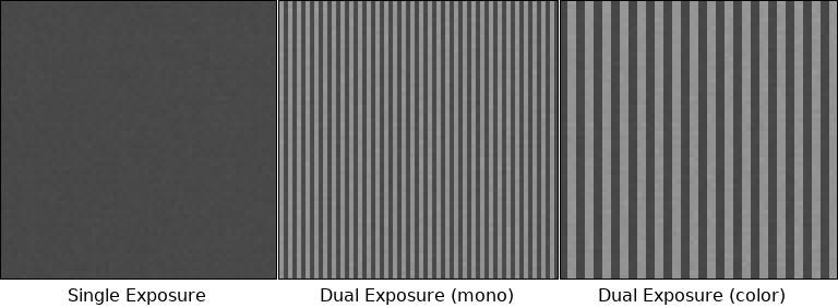
In monochrome mode this Dual Exposure HDR mode affects even and odd columns as they can have different exposure times within the same image. In colour mode (to maintain the bayer pattern) this HDR mode affects two columns each: | |||
[[File:Dual_exposure_collage.png]] | |||
===Piecewise Linear Response (PLR) HDR mode=== | |||
TODO | |||
===Alternating Exposure time HDR mode=== | |||
TODO | |||
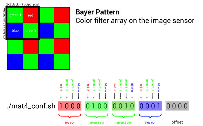
==mat4_conf.sh== | |||
Read the details about the [[Matrix Color Conversion]] math/implementation. | |||
To set the 4x4 color conversion matrix, you can use the mat4_conf.sh script: | |||
The default configuration: | |||
./mat4_conf.sh 1 0 0 0 0 1 0 0 0 0 1 0 0 0 0 1 0 0 0 0 | |||
''' | |||
Please note that in current AXIOM Beta firmware the mat4 order is changed and the default matrix is: | |||
./mat4_conf.sh 0.3 0.3 0.3 0.3 0 0 0 1 0 0.42 0.42 0 1 0 0 0 | |||
This will be changed to reflect the documentation again soon.''' | |||
With the Black Magic Video Assist (BMVA), a nicer matrix (ie better skin color, less greenish): | |||
./mat4_conf.sh 0.3 0.3 0.3 0.3 0 0 0 1 0 0.3 0.3 0 1 0 0 0 | |||
This 4x4 conversion matrix is a very powerful tool and allows to do things like mixing color channels, reassigning channels, applying effects or doing white balancing. | |||
TODO: order is blue, green, red! | |||
[[File:Mat4-conf-illustration-01.jpg | 700px]] | |||
'''4x4 Matrix Examples:''' | |||
<pre class="code"> | |||
./mat4_conf.sh 1 0 0 0 0 1 0 0 0 0 1 0 0 0 0 1 0 0 0 0 # unity matrix but not optimal as both green channels are processed separately | |||
./mat4_conf.sh 1 0 0 0 0 0.5 0.5 0 0 0.5 0.5 0 0 0 0 1 0 0 0 0 # the two green channels inside each 2x2 pixel block are averaged and output on both green pixels | |||
./mat4_conf.sh 0 0 0 1 0 1 0 0 0 0 1 0 1 0 0 0 0 0 0 0 # red and blue are swapped | |||
./mat4_conf.sh 1 0 0 0 0 1 0 0 0 0 1 0 0 0 0 1 0.5 0 0 0 # red 50% brigther | |||
./mat4_conf.sh 1 0 0 0 0 1 0 0 0 0 1 0 0 0 0 1.5 0 0 0 0 # blue multiplied with factor 1.5 | |||
./mat4_conf.sh .25 .25 .25 .25 .25 .25 .25 .25 .25 .25 .25 .25 .25 .25 .25 .25 0 0 0 0 # black/white | |||
./mat4_conf.sh -1 0 0 0 0 -0.5 -0.5 0 0 -0.5 -0.5 0 0 0 0 -1 1 1 1 1 # negative | |||
</pre> | |||
==Image Histogram Data== | |||
To read and output histogram data from the AXIOM Beta's live image a tool called cmv_hist3 (Firmware 1.0) / axiom_hist (Firmware 2.0) is available inside the AXIOM Beta. | |||
Firmware 1.0 example: | |||
<pre class="code"> | |||
./cmv_hist3 -h | |||
This is ./cmv_hist3 V1.4 | |||
Options are: | |||
-h print this help message | |||
-s acquire snapshot | |||
-b <num> number of bins | |||
-d <num> decimation factor | |||
-r <num> number of rows | |||
-C <prc> center sample area | |||
-B <val> register mapping base | |||
-S <val> register mapping size | |||
</pre> | |||
The output in 12 bit mode (default) are values in 4096 lines and 4 columns (R, G, B, GB channels): | |||
<pre class="code"> | |||
... | |||
2 2 1 81 | |||
7 5 2 105 | |||
4 6 6 142 | |||
5 6 2 149 | |||
9 3 7 198 | |||
10 8 11 227 | |||
9 5 13 275 | |||
11 3 14 363 | |||
9 6 19 390 | |||
12 14 19 470 | |||
18 23 27 542 | |||
13 19 32 675 | |||
21 12 46 782 | |||
28 20 54 865 | |||
32 30 68 987 | |||
... | |||
</pre> | |||
=Motion Picture (Video) Recording/Monitoring= | |||
The camera internal microSD cards are good to capture still images but the bandwidth is not sufficient to capture moving images. For moving images we utilize the HDMI compatible output for monitoring but also for external and internal recording. | |||
== | ==HDMI Introduction== | ||
HDMI is a two-way communication protocol and supports a ton of different formats/frequencies/specs. | |||
Many monitors/recorders only support a subset of these formats and expect signals to conform to certain values. These values are not documented publicly so we are currently in the process of debugging device compatibility one by one. The good thing is that its a pure software thing and we can add support and test compatibility with additional devices as we go. | |||
In general we discovered that monitors are more flexible when it comes to HDMI (TMDS) frequencies as they just "tune" into (sync to) the provided clock/data rate. External recorders expect signals to be in a much more strict/narrow range and will not work (show "no signal") if there is a minor deviation. | |||
Watch this 33C3 talk by Tim Ansell about "Dissecting HDMI": https://media.ccc.de/v/33c3-8057-dissecting_hdmi to get insight into how HDMI works. | |||
The AXIOM Beta has two plugin module slots so two HDMI outputs can be operated in parallel. | |||
==External HDMI Recording/Monitoring== | |||
The AXIOM Beta HDMI plugin module outputs 1080p60 or 1080p50 by default in (RGB 4:4:4) mode. | |||
1080p25 or 1080p30 can also be configured (see below). | |||
We noticed that quite a few HDMI recorder devices have trouble with RGB mode. | |||
We maintain a [[list of compatible HDMI devices]]. | |||
We also noticed that sometimes the HDMI is not "hot-pluggable" : you'd need to plug the HDMI recorder/monitor to the AXIOM beforehand and turn it on before turning the AXIOM on. | |||
Settings for VSync, HSync, etc. inside the AXIOM Beta (Firmware 1.0) can be found in: | |||
/root/gen_init.sh | |||
For example the Atomos SHOGUN was found to work with these HDMI parameters: | |||
<pre class="code"> | |||
scn_reg 0 2200 # total_w | |||
scn_reg 1 1125 # total_h | |||
scn_reg 2 60 # total_f | |||
scn_reg 4 262 # hdisp_s | |||
scn_reg 5 2182 # hdisp_e | |||
scn_reg 6 45 # vdisp_s | |||
scn_reg 7 1125 # vdisp_e | |||
scn_reg 8 0 # hsync_s | |||
scn_reg 9 2100 # hsync_e | |||
scn_reg 10 4 # vsync_s | |||
scn_reg 11 9 # vsync_e | |||
scn_reg 32 252 # pream_s | |||
scn_reg 33 260 # guard_s | |||
scn_reg 34 294 # terc4_e | |||
scn_reg 35 296 # guard_e</pre> | |||
Currently it is not possible to alter TMDS and Clock frequencies from the userspace (requires new FPGA bitstream). | |||
For the firmware there are two modes available, the 30Hz and 60Hz variant. You can switch between them quite easily. | |||
cmv_hdmi3.bit is the FPGA bitstream loaded for the HDMI interface. We use symlinks to switch this file easily. | |||
Before doing this, don't forget to check if the files (cmv_hdmi3_60.bit or cmv_hdmi3_30.bit) really exist in the /root folder. | |||
The output is always in 8bpc RGB color space without subsampling (4:4:4). Not all capture devices can handle this. | |||
'''Note:''' Modes like YCrCb, etc. are currently not supported. | |||
There is now a new gateware that allows filling data islands in the HDMI signal (elements of data that are outside the visible image containing meta data). | |||
Download: http://vserver.13thfloor.at/Stuff/AXIOM/BETA/HDMIDI/ | |||
./ | ./infoframe.py | ./makepkt.py | ./packet.py | ||
will generate the AVI info frame, create a packet and upload it to the packet buffer | |||
./vendorframe.py | ./makepkt.py | ./packet.py /dev/stdin 32 | |||
will do similar for a vendor frame (AXIOM BETA RAW) and upload it into the second slot of the packet buffer. | |||
There are as many slots as the vertical sync is long, but by default the packets are NULL packets which doesn't hurt. The new sync inversion bits (OSCN(5)(31) und OSCN(4)(31)) can be used to create a more common inverted sync without messing with the sync start und end position | |||
Changes to the respective scripts are not done yet, testing is still ongoing. | |||
===HDMI Overlays=== | |||
This section covers the mimg version 1.8 (see https://github.com/apertus-open-source-cinema/beta-software/tree/master/software/processing_tools/mimg), not the previous 1.6. | |||
AXIOM Beta features a full HD framebuffer that can be altered from the Linux userspace and is automatically "mixed" with the real time video from the image sensor on HDMI outputs. | |||
The overlay could also be used to draw live histograms/scopes/HUD or menus. | |||
The overlay in more recent firmware revisions supports alpha channel transparency. | |||
Overlays are not visible on raw12 images captured with cmv_snap3, only on HDMI output. | |||
== | ====Internals==== | ||
The raw memory image is saved the following way: <ch0/12bit><ch1/12bit><ch2/12bit><ch3/12bit><overlay/16bit> | |||
That means for every 4 sensels there is only one overlay pixel. Meaning while the CMV12000 image sensor is 4Kx3K the overlay is Full HD (1080p). | |||
====Prepare Images==== | |||
Convert 24bit PNG (1920x1080 pixels) with transparency to AXIOM Beta raw format: | |||
convert input.png rgba:output.rgb | |||
'''Note:''' This image format is different from [[RAW12]] (See Section 8) | |||
====mimg==== | |||
''mimg'' is software running on the camera that's used to load/alter anything related to overlays or test images. | |||
Source Code: https://github.com/apertus-open-source-cinema/beta-software/tree/master/software/processing_tools/mimg | |||
<pre class="code">This is ./mimg V1.8 | |||
options are: | |||
-h print this help message | |||
-a load all buffers | |||
-o load as overlay | |||
-O load as color overlay | |||
-r load raw data | |||
-w use word sized data | |||
-D <val> image color depth | |||
-W <val> image width | |||
-H <val> image height | |||
-P <val> uniform pixel color | |||
-T <val> load test pattern | |||
-B <val> memory mapping base | |||
-S <val> memory mapping size | |||
-A <val> memory mapping address</pre> | |||
'''Examples''' | |||
./ | clear overlay: | ||
./mimg -a -o -P 0 | |||
load monochrome overlay: | |||
./mimg -o -a file.raw | |||
load color overlay: | |||
./mimg -O -a file.raw | |||
enable overlay: | |||
gen_reg 11 0x0104F000 | |||
disable overlay: | |||
gen_reg 11 0x0004F000 | |||
'''Old overlays''' | |||
Overlays for mimg 1.6 are not compatible anymore. You can use | |||
convert -size 1920x1080 -depth 6 rgba:overlay_04.rgb overlay_04.png | |||
... to convert them to PNG before continuing with the preparation above. | |||
==Internal Raw Recording== | |||
The AXIOM Recorder is currently in development but has been demonstrated to work to record uncompressed 12 bit raw in UHD and 4K mode at 24, 25 and 30 frames per second. | |||
The AXIOM Recorder is a small computer connected to the AXIOM Beta via HDMI, we use the HDMI video stream to transport our own custom raw image data from the camera. This stream needs to be repacked or post processed on the AXIOM Recorder to acquire the actual raw image sequence (RAW12 sequence). First software prototypes did this after recording, newer versions do it on-the-fly while recording. | |||
The | The documentation is collected on the [[AXIOM_Beta/Raw_Recording | AXIOM Raw Recording]] page. | ||
==Frame Rates== | |||
-- | ===1080p60/1080p50 Mode=== | ||
Firmware 1.0: | |||
<pre class="code"> | |||
rm -f cmv_hdmi3.bit | |||
ln -s cmv_hdmi3_60.bit cmv_hdmi3.bit | |||
sync | |||
reboot now | |||
</pre> | |||
Firmware 2.0: | |||
become root: | |||
sudo su | |||
run (if you ran axiom_start.sh already before): | |||
axiom_halt.sh | |||
Create a copy of axiom_start.sh with a new name eg. axiom_start60.sh | |||
cp $(which axiom_start.sh) axiom_start60.sh | |||
Make it executeable: | |||
chmod +x axiom_start60.sh | |||
In it replace this line: | |||
echo axiom_fpga_main.bin > /sys/class/fpga_manager/fpga0/firmware | |||
by this line (choosing appropriate files: _60 for 50p/60p modes): | |||
echo cmv_hdmi3_dual_60.bin > /sys/class/fpga_manager/fpga0/firmware | |||
execute the new script: | |||
axiom_start60.sh | |||
== | ===1080p30/1080p25 Mode=== | ||
Firmware 1.0: | |||
<pre class="code"> | |||
rm -f cmv_hdmi3.bit | |||
ln -s cmv_hdmi3_30.bit cmv_hdmi3.bit | |||
sync | |||
reboot now | |||
</pre> | |||
Firmware 2.0: | |||
become root: | |||
sudo su | |||
run (if you ran axiom_start.sh already before): | |||
axiom_halt.sh | |||
Create a copy of axiom_start.sh with a new name eg. axiom_start30.sh | |||
cp $(which axiom_start.sh) axiom_start30.sh | |||
Make it executeable: | |||
chmod +x axiom_start30.sh | |||
In it replace this line: | |||
echo axiom_fpga_main.bin > /sys/class/fpga_manager/fpga0/firmware | |||
by this line (choosing appropriate files: _30 for 50p/60p modes): | |||
echo cmv_hdmi3_dual_30.bin > /sys/class/fpga_manager/fpga0/firmware | |||
execute the new script: | |||
axiom_start30.sh | |||
===Generator and HDMI Output=== | |||
Independent of the firmware you can switch the rate of the generator. In setup.sh you can change the generator resolution and framerate. | |||
After changing the generator mode, make sure to restart it: | |||
./halt_manual.sh && ./kick_manual.sh | |||
<pre class="code"> | |||
./gen_init.sh 1080p60 | |||
./gen_init.sh 1080p50 | |||
./gen_init.sh 1080p25 | |||
</pre> | |||
To enable the Atomos Shogun mode (also works with other recorders): | |||
./gen_init.sh SHOGUN | |||
1080p25 mode is known to work on the Shogun if using the SHOGUN profile and then setting | |||
scn_reg 0 2640 | |||
In Shogun mode, the exposure (shutter) is synced to the output frame rate, but can be a multiple, i.e. with 60FPS output, it can be 60, 30, 20, 15, 12, ... The exposure time (shutter angle if divided by FPS) is entirely controlled by the sensor at the moment. | |||
'''Note:''' The firmware controls the shutter, not the generator. | |||
In the future, this will be combined and processed by only one piece of software. | |||
===Stopping and Starting HDMI Live-stream=== | |||
To utilize the below functions you need to first run: | |||
Firmware 1.0: | |||
. ./cmv.func | |||
Note that the following commands start/stop the continuous image acquisition - not the HDMI link in general. | |||
Stop HDMI live stream: | |||
Firmware 1.0: | |||
fil_reg 15 0 | |||
Firmware 2.0: | |||
axiom_sequencer_stop.sh | |||
Start HDMI live stream: | |||
Firmware 1.0: | |||
fil_reg 15 0x01000100 | |||
Firmware 2.0: | |||
axiom_sequencer_start.sh | |||
===cmv_perf3=== | |||
To check the frame rate of the the image acquisition and HDMI output you can run the performance tool (takes a few seconds to gather data): | |||
Firmware 1.0: | |||
./cmv_perf3 | |||
Firmware 2.0 | |||
axiom_perf | |||
Note that the framerate can drop if the exposure time is too long. | |||
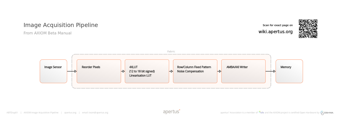
==Image Acquisition Pipeline== | |||
[[File:ABTDiap01- AXIOM Image Acquisition Pipeline.png | 1150px]] | |||
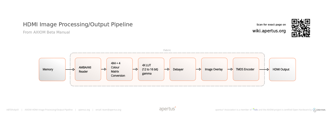
==HDMI Image Processing/Output Pipeline== | |||
[[File:ABTDhdip01- AXIOM HDMI Image Processing and Output Pipeline.png | 1150px]] | |||
==FPGA Bitstream / Gateware related Notes== | |||
The FPGA drives the real time image acquisition and processing. A Bitstream or Gateware is the "software" loaded into the FPGA. | |||
To check the date of a gateware loaded into the FPGA run (Firmware 2.0, after image sensor initation): | |||
axiom_gateware_versiondate.sh | |||
The output shows the date and time of when the gateware bitstream was generated. | |||
C93157BB = 25.02.24 21:30:59 | |||
=Maintenance= | |||
==Firmware Updating/Backup/Restore== | |||
The operating system is based on an embedded Arch Linux. The entire AXIOM Beta firmware is stored on a Micro SD card. This means the camera's operating system can be swapped out and if anything goes wrong external recovery of the camera entire software is possible. It also means that experimental features can be tried and tested simply by popping a different Micro SD card into the camera. | |||
AXIOM Beta | We recommend using the [[AXIOM Beta Firmware Version 2.0]], which is automatically built when sources on github change, some documentation here on the wiki might be related to Firmware 1.0 but we are trying to update everything here. | ||
For a full guide about firmware flashing/backup see: [[AXIOM_Beta/Firmware_Flashing | Firmware Flashing]] | |||
==Micro SD Slots== | |||
The Microzed features a Micro SD card slot that holds the cameras operating system. There is a second Micro SD card slot on the AXIOM Beta Power Board designated for user data. Both slots support SDHC cards so the maximum size is 32GB per slot. | |||
On the AXIOM Beta, like most embedded systems there is no BIOS to setup the devices and instead a device tree is used to describe the hardware configuration. The second Micro SD slot is disabled in the device tree by default and needs to be enabled to be used - mainly because it doesn't have a direct card detect input and some kernels start generating a lot of dmesg messages when there is no card present. | |||
This device tree can be found in /boot and will be loaded from the bootloader and supplied to the Linux kernel on startup. | |||
There should be a human readable version in /boot as well named '''devicetree.dts''' which you can view and edit. Look for a ps7_sd_1 entry which most likely has a 'status = "disabled";' which needs to be modified to "okay". After that the devicetree needs to be compiled into machine readable format (devicetree.dtb) with the device tree compiler. | |||
Something like: | |||
dtc -I dts -O dtb -o /boot/devicetree.dtb /boot/devicetree.dts | |||
A reboot is required to load the new device tree. | |||
''' | '''Note that we strongly recommend to make a full backup of your Micro SD card before modifying the device tree because if anything does not work as expected your AXIOM Beta will not boot anymore.''' | ||
==Image Sensor cleaning== | |||
[[File:Green_Swabs_200X200_B.png | 500px| thumb | 550px]] | |||
We are using the green sensor cleaning swabs (See right). | |||
It comes with two cleaning solutions: one for dust and one for any grease based residues (finger prints, etc.). | |||
We have seen best results first using the "smear away" solution and then using the "dust away" solution afterwards. It can also help to use a clean swab without any liquid to clean away any of the cleaning liquid residue as 3rd step if required. | |||
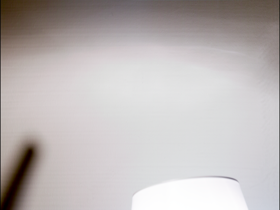
In this section we try to collect typical sensor contamination images and guide on how to spot and get rid of them. | |||
The best lighting conditions to spot contamination on an AXIOM Beta image seems to be mid grey, you can take off or slightly turn the lens to make sure the contamination is not on any lens glass element. | |||
Vertical streaks: | |||
[[File:Vertical-streaks.png | 550px]] | |||
These are the result of using the dust cleaning solution on the sensor. Likely the streaks are oil based contaminations. Use the red bottle "smear away" and a swap to clean the sensor. | |||
=Hardware= | |||
See [[Research_Pending]] for AXIOM Beta/OLPF (Optical Low Pass Filter), and [[Hardware/Misc]] for Cable Armour / DIY Flourescent Area Light / Integrating Sphere / Quicklock Plate / Rods / Rosettes / V-Mount / Various mechanical links. | |||
See [[Research_Pending]] for AXIOM Beta/OLPF (Optical Low Pass Filter), and [[Hardware/Misc]] for Cable Armour / DIY Flourescent Area Light / Integrating Sphere / Quicklock Plate / Rods / Rosettes / V-Mount / Various mechanical links. | |||
{{:AXIOM_Beta/Camera_Structure}} | |||
[[File: | [[File:Beta_Assembly.jpg| thumb | 350px | AXIOM Beta Developer Kit.]] | ||
==GPIO== | |||
There are a number of options with GPIO with different pros and cons on the AXIOM Beta. | |||
===Use some kind of USB device=== | |||
This is probably the most versatile and straight forward approach to get some kind of button or dial attached to the AXIOM Beta with the least danger to the hardware. | |||
There are Single USB buttons, mini Keyboards (3-9 buttons) and volume knobs (usually one button with a dial) which can be easily attached to the camera and will usually produce some kind of keyboard events. | |||
===Use the PS GPIOs on the Microzed=== | |||
Note that this and all the following points need to be done with proper care, as the directly connected GPIOs will be sensitive to ESD, short circuits and over-voltage. | |||
Header J5 on the Microzed is a Digilent PMOD compatible 2x6 pin header which provides a number of PS GPIO pins. | |||
On the AXIOM Beta, they are connected to the second SD slot on the Power Board, but if the SD slot is not used, they can be used for other purposes. | |||
This could be simple Buttons connecting to GND or to the PS supply rail (both also on the header) or they could be more complex stuff via IIC or SPI. | |||
===Use the Shield GPIOs on the Mainboard Shield=== | |||
Those are MachXO2 GPIOs and can be checked via JTAG or by adding appropriate Routing Fabric code to evaluate whatever sensor available. | |||
This is at the moment rather complicated to do but should become simpler in the future once we have generic routing fabric IO code in place. | |||
===Create an IO Plugin Module=== | |||
Those are PL GPIOs so they do not require any MachXO2 code to be checked, but they are somewhat tricky to handle as the gateware needs to be modified and the GPIOs are paired up into LVDS pairs. | |||
===Create an IO Shield=== | |||
This is probably the best solution after the USB attached devices, as the shield can take care of GPIO isolation and thus protect any inputs and outputs from shorts or ESD discharges. | |||
==EEPROM== | ==EEPROM== | ||
| Line 2,316: | Line 1,307: | ||
All of the PCBs we created for the AXIOM Beta (aside from the AXIOM Beta Main Board) have an onboard [https://en.wikipedia.org/wiki/EEPROM EEPROM]. These chips provide between 4KB and 16KB of non-volatile memory. These EEPROMs are used to store unique identifiers for each board/type. In a modular stack of PCBs the camera firmware can read the EEPROMs of each PCB and identify which boards, versions and revisions are attached (different board versions might need different drivers/firmware elements). | All of the PCBs we created for the AXIOM Beta (aside from the AXIOM Beta Main Board) have an onboard [https://en.wikipedia.org/wiki/EEPROM EEPROM]. These chips provide between 4KB and 16KB of non-volatile memory. These EEPROMs are used to store unique identifiers for each board/type. In a modular stack of PCBs the camera firmware can read the EEPROMs of each PCB and identify which boards, versions and revisions are attached (different board versions might need different drivers/firmware elements). | ||
| Line 2,380: | Line 1,369: | ||
128 byte UUID | 128 byte UUID | ||
==Power== | ==Power== | ||
| Line 2,391: | Line 1,377: | ||
The camera takes two 5V inputs (1x Microzed, 1x rest of electronics) and draws 4A max. Power consumption depends on operation and is in the 10-20 W range typically. | The camera takes two 5V inputs (1x Microzed, 1x rest of electronics) and draws 4A max. Power consumption depends on operation and is in the 10-20 W range typically. | ||
| Line 2,404: | Line 1,388: | ||
For battery power see [[Power]] or [https://lab.apertus.org/T736 Battery System] on Labs. | For battery power see [[Power]] or [https://lab.apertus.org/T736 Battery System] on Labs. | ||
==Image Sensor Frontend== | ==Image Sensor Frontend== | ||
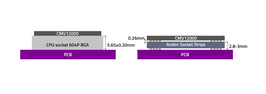
There are two versions of the CMV12000 Sensor Frontend PCB, one with a ZIF CPU 604P GBA socket and one with a custom socket ( 2 strips) manufactured by Andon: | |||
<center> | <center> | ||
| Line 2,420: | Line 1,402: | ||
</center> | </center> | ||
| Line 2,433: | Line 1,413: | ||
{| class="wikitable" | {| class="wikitable" | ||
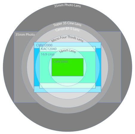
! style="text-align: right; font-weight: bold;" | | ! style="text-align: right; font-weight: bold;" | Image Sensor Diameter | ||
! 16mm | ! 16mm | ||
! Four Thirds | ! Four Thirds | ||
| Line 2,444: | Line 1,424: | ||
|- | |- | ||
| style="text-align: right; font-weight: bold;" | Model | | style="text-align: right; font-weight: bold;" | Model | ||
| [ | | [http://www.cmosis.com/products/product_detail/cmv2000 CMV2000] | ||
| [ | | [http://www.onsemi.com/pub_link/Collateral/KAC-12040-D.PDF KAC12040] | ||
| [ | | [http://www.cmosis.com/products/product_detail/cmv12000 CMV12000] | ||
|- | |- | ||
| style="text-align: right; font-weight: bold;" | Development Status | | style="text-align: right; font-weight: bold;" | Development Status | ||
| Line 2,503: | Line 1,483: | ||
| | | | ||
| 200 ISO | | 200 ISO | ||
| ~ | | ~ 200 - 800 ISO | ||
|- | |- | ||
| style="text-align: right; font-weight: bold;" | Max Frame Rate @ Bit Depth | | style="text-align: right; font-weight: bold;" | Max Frame Rate @ Bit Depth | ||
| Line 2,512: | Line 1,492: | ||
| style="text-align: right; font-weight: bold;" | More info | | style="text-align: right; font-weight: bold;" | More info | ||
| | | | ||
* [http://www.cmosis.com | * [http://www.cmosis.com/products/product_detail/cmv2000 Official Specs] | ||
| | | | ||
* [http://www.onsemi.com/pub_link/Collateral/KAC-12040-D.PDF Datasheet] | * [http://www.onsemi.com/pub_link/Collateral/KAC-12040-D.PDF Datasheet] | ||
| | | | ||
* [https://github.com/apertus-open-source-cinema/ | * [https://github.com/apertus-open-source-cinema/beta-hardware/tree/master/Datasheets Datasheets] | ||
* [http://www.cmosis.com | * [http://www.cmosis.com/products/product_detail/cmv12000 Official Specs] | ||
* [http://www.magiclantern.fm/forum/index.php?topic=11787.msg129672#msg129672 Sensor Noise Analysis] | * [http://www.magiclantern.fm/forum/index.php?topic=11787.msg129672#msg129672 Sensor Noise Analysis] | ||
|} | |} | ||
The community is keeping a log of sensors that | The community is keeping a log of sensors that could be potentially interesting as future AXIOM modules. See [[Image Sensor Table]]. | ||
==Lens Mounts== | ==Lens Mounts== | ||
AXIOM Beta is outfitted with an E-Mount | AXIOM Beta Developer Kit is outfitted with an E-Mount currently. We provide adapters for Canon EF & Nikon F mounts. Further adapters like PL, etc are widely available. | ||
We have not had a chance to test any speedbooster directly on the camera but are keen on community reports here. | We have not had a chance to test any speedbooster directly on the camera but are keen on community reports here. | ||
| Line 2,587: | Line 1,543: | ||
| colspan="2" | 44 mm | | colspan="2" | 44 mm | ||
| 19.25 mm | | 19.25 mm | ||
|} | |} | ||
More Details: [[Lens Mounts]] | More Details: [[Lens Mounts]] | ||
| Line 2,605: | Line 1,555: | ||
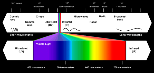
Image sensors are typically sensitive to a wider spectrum than the human eye. So we use an Infrared (IR) / Ultraviolet (UV) cut off filter that acts as an optical bandpass. These filters work with a reflective coating that cuts below 390nm and above 750nm. | Image sensors are typically sensitive to a wider spectrum than the human eye. So we use an Infrared (IR) / Ultraviolet (UV) cut off filter that acts as an optical bandpass. These filters work with a reflective coating that cuts below 390nm and above 750nm. | ||
We | We ship these filters with AXIOM Beta Developer Kits: https://www.amazon.de/Haida-Digital-Slim-Filter-inkl/dp/B00CGGZ786 | ||
With the AXIOM Beta developer kits we use this filter "externally" - screwed to the lens thread. With very wide angle lenses (< 16mm focal length) this can lead to visible color shift vignetting. | With the AXIOM Beta developer kits we use this filter "externally" - screwed to the lens thread. With very wide angle lenses (< 16mm focal length) this can lead to visible color shift vignetting. | ||
| Line 2,612: | Line 1,562: | ||
Proposal: Buy 100x100mm filter from http://www.uqgoptics.com/catalogue/Filters/IR_CUT_OFF_FILTERS.aspx?subCatOrCatName=ir_cut_off_filters and cut into 3x3 pieces | Proposal: Buy 100x100mm filter from http://www.uqgoptics.com/catalogue/Filters/IR_CUT_OFF_FILTERS.aspx?subCatOrCatName=ir_cut_off_filters and cut into 3x3 pieces | ||
---- | ---- | ||
[[Category:CMV12000]] | [[Category:CMV12000]] | ||
| Line 2,623: | Line 1,571: | ||
[[category: plugins]] | [[category: plugins]] | ||
[[category: Shields]] | [[category: Shields]] | ||
[[category: | [[category: Manuals]] | ||
Latest revision as of 12:33, 13 June 2024
Preamble
- For all resources related to the camera see AXIOM Beta Main Page.
- To see how community members are using the camera see Case Studies.
- For an introduction to the camera's components see AXIOM Beta Camera Structure.
- For sample still/video files, camera availability, socials and other important stuff see Useful Links.
Should you experience difficulties or have a query and require live assistance please come to our IRC channel and see if a community member is currently around for live chat: https://www.apertus.org/irc-chat Otherwise please email us through the contact details.
To use this manual a deep technical understanding of the AXIOM is not required. You need to use Linux though and it helps if you have used a commandline before.
1 General Information
1.1 Safety Precautions
This device and its software is provided without warranty of Merchantability or fitness for any particular purpose. apertus° assumes no responsibility or liability for any loss or damage as a result of the use or misuse. USE AT YOUR OWN RISK. You have root access to this system and can potentially brick and damage the hardware from the command line interface - be responsible and when in doubt consult with apertus° before doing anything potentially harmful to your camera.
Our hardware is not weather sealed so use extra caution when operating the equipment outdoors. In particular sea/salt water spray is very harmful to electronics.
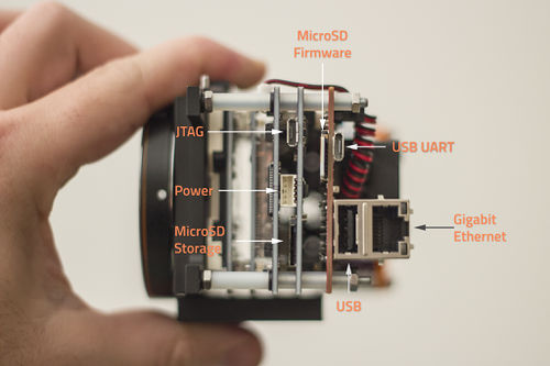
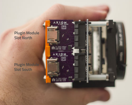
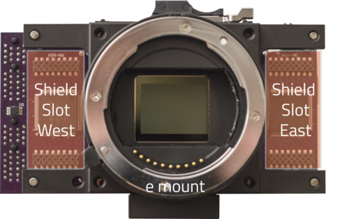
1.2 AXIOM Beta Connector Overview
2 Operating Basics
2.1 Prepare Your AXIOM Beta Camera for Use
0. Flash the firmware → AXIOM_Beta_Firmware_Version_2.0
- We started shipping AXIOM Beta Developer Kits with Wi-Fi USB sticks. This allows you to connect your device to the Wi-Fi access point of the camera after it booted to get SSH access or open the web interface in your browser without having to deal with cables and IP address setups on your router.
- Alternatively: Use a micro-USB cable to connect the camera's MicroZed development board (USB UART) to a computer. The MicroZed board is the rearmost, red PCB (There is another micro-USB socket on the Power Board, but that is the JTAG Interface).
- Alternatively: Connect the Ethernet port on the MicroZed to an Ethernet port on your computer. You might have to use an Ethernet adapter on newer, smaller machines which often come without a native Ethernet port.
- Connect the AC adapter to the camera's Power Board. (to power the camera off at a later point, you need not disconnect the adapter from the board but can just unplug the cord from the adapter.)
Each camera ships with an external AC power supply that provides 5V and 6-8A. The Beta requires two 5V inputs (one for the Microzed, one for the rest of the hardware). Each 5V supply should be able to provide at least 2-3A. The total power consumption in normal operation was measured to be around 10W. During boot up there are spikes of higher power consumption.
2.1.1 LED Indicators
Once the AXIOM is powered on, you should see a green LED permanentely ON and a red LED with a heart-beat pattern.
- the green LED is directly connected to the MicroZed Power
- the red LED is controlled by the PS (Linux)
- the blue LED (see below) flashes with every triggered image acquisition.
NOTE : If the red LED is permanently ON or not there, chances are good that the SD card is bad/missing and the MicroZed does not boot.
2.2 Prepare Your Computer for Use With Your Camera
To communicate with your AXIOM Beta camera you will send it instructions via your computer's command line.
In case you have not worked with a shell (console, terminal) much or ever before, we have prepared detailed instructions to help you get you set up. The steps which need to be taken to prepare your machine sometimes differ between operating systems, so pick the ones that best apply to you(r system).
Note: Dollar signs $ placed in front of commands are not meant to be typed in, they denote the command line prompt (a signal indicating the computer is ready for user input). It is used in documentation to differentiate between commands and the output resulting from commands. The prompt might look different on your machine (e.g. an angled bracket >) and be preceded by your user name, computer name or the name of the directory that you are currently inside.
2.2.1 WiFi Access Point Setup
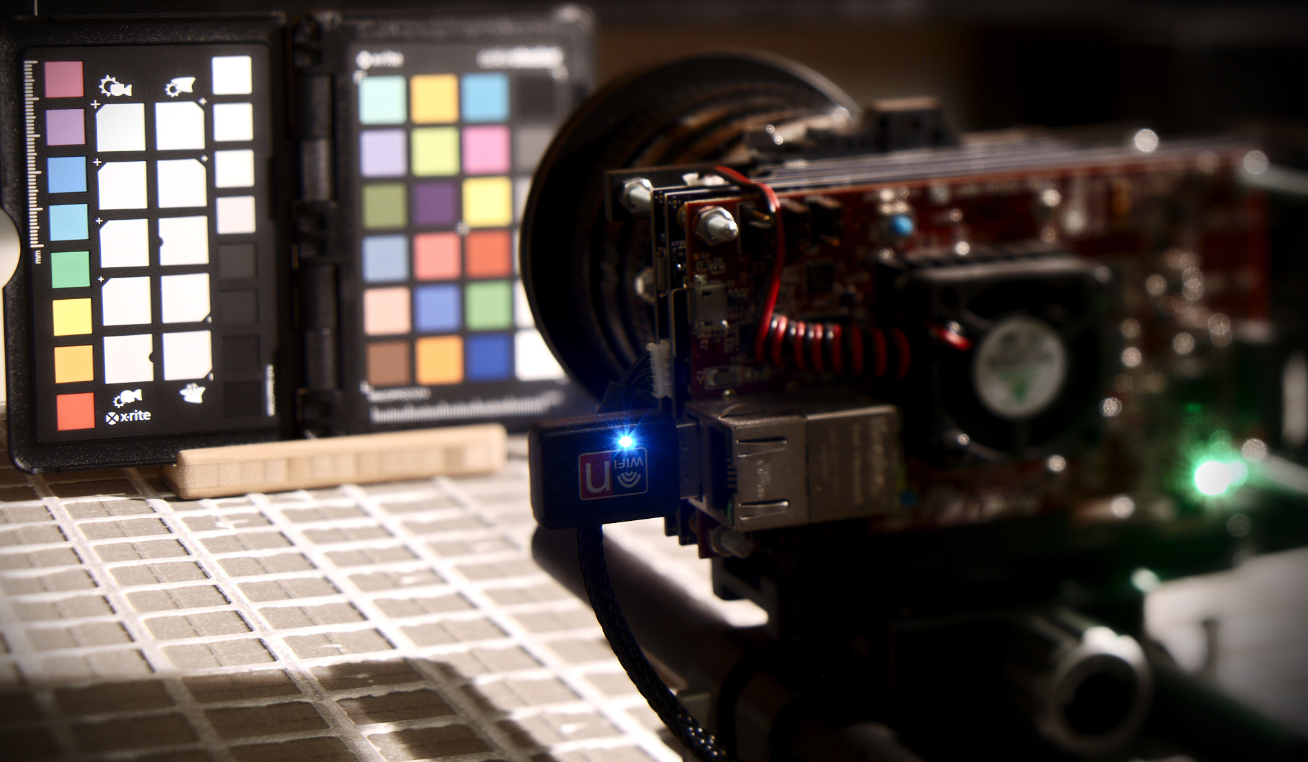
Connecting a USB wifi dongle (that supports Soft-AP) to the AXIOM Beta USB port allows controlling the camera via wireless connection on Firmware 2.0.
The following devices have been tested so far:
| Device | Wifi Chip | Cost | Comment |
|---|---|---|---|
| Think Penguin TPE-N150USB | Atheros AR9271 | 54$ | works out of the box with FW2.0 |
| Technoethical TET-N150 | Atheros AR9271 | 50€ | works out of the box with FW2.0 |
| Edimax EW-7811UN | Realtek RTL8188CUS | 8€ | works out of the box with FW2.0, connection speed is very slow,
alternative rlt8xxxu driver does not support AP mode |
| TB® | Ralink 5370 | 9€ | works out of the box with FW2.0 |
| Logilink WL0145A | Realtek RTL8188EUS | does not work | |
| tp-link TL-WN725N | Realtek RTL8188EUS | does not work | |
| Dootoper AC1200 | RTL88x2bu AC1200 | does not work | |
| tp-link Archer T2U nano | RTL8811AU | does not work | |
| EDUP AC1200 | RTL88x2bu AC1200 | does not work | |
| MECO ELEVERDE WiFi Adapter | Realtek RTL8188GU | does not work | |
| Agedate WLAN Adapter | RTL88x2bu AC1200 | does not work | |
| Logilink WL0084E | does not work | ||
| TP-Link UB400 Nano | does not work |
In a recent Firmware 2.0 the wifi accesspoint setup is already preconfigured and will start automatically after the AXIOM Beta has booted. This means the AXIOM Beta itself will become an access point you can connect to. The default SSID (wireless network's name) is called "axiom". Once connected the DNS entry for your camera is configured as "axiom.camera".
This means you can ssh to the camera like this:
Limited User:
ssh operator@axiom.camera
Administrative User:
ssh root@axiom.camera
Or you can open the web user interface running on the camera by opening axiom.camera in your browser.
Note that some operating systems will complain about not having internet connectivity after connecting to the axiom hotspot and might automatically switch to your home/office WIFI access point again to provide you with internet connectivity.
2.2.1.1 Connecting the AXIOM Beta to another Wifi Access Point
The wireless adapter cannot only create an access point you can also connect the AXIOM Beta to an existing access point. To do this the tool nmtui is preinstalled in the cameras firmware.
nmtui can be started via serial console for example and the first "page" looks like this:
You can then activate a connection, choose an existing Wifi SSID and enter the password to connect:
ifconfig can be used afterwards to check if the AXIOM Beta received an IP successfully from the connected wifi network. The AXIOM Beta will remember the passwords to networks you connected successfully and connect to them automatically on the next boot.
2.2.1.2 WiFi Access Point Setup Details
If you want to dive deeper:
Check your wifi card:
ifconfig
Turn on wifi card:
ifconfig wlan0 up
Search wifi essid/hotspot name:
iwlist wlan0 scan
Setting up Essid and password:
WEP
iwconfig wlan0 essid "yourhotspotname" key yourpassword
ASCII
iwconfig wlan0 essid "yourhotspotname" key s:asciikey
WPA2 (tested and working) update mirrors database (it is required to connect to the Internet via Ethernet):
pacman -Syy
install wpa_supplicant:
pacman -S wpa_supplicant
Configuration with wpa_passphrase - https://wiki.archlinux.org/index.php/WPA_supplicant create basic configuration file MYSSID = name of your wireless network passphrase = password to connect to your wireless network
wpa_passphrase MYSSID passphrase > /etc/wpa_supplicant/example.conf
ip link set dev wlan0 up
wpa_supplicant -B -i wlan0 -c /etc/wpa_supplicant/example.conf
if nl80211 driver does not support the given hardware. The deprecated wext driver might still support the device:
wpa_supplicant -B -i wlan0 -D wext -c /etc/wpa_supplicant/example.conf
dhcpcd wlan0
Autostart connect https://wiki.archlinux.org/index.php/netctl copy config from example:
cp /etc/netctl/example/wireless-wpa /etc/netctl/wireless-wpa
edit the config for you network (interface/ESSID/key):
nano /etc/netctl/wireless-wpa
First manually check that the profile can be started successfully with:
netctl start wireless-wpa
If the above command results in a failure, then use
journalctl -xn
netctl status profile
to obtain a more in depth explanation of the failure. (profile might already been started)
Enable:
netctl enable wireless-wpa
This will create and enable a systemd service that will start when the computer boots. Changes to the profile file will not propagate to the service file automatically. After such changes, it is necessary to reenable the profile:
netctl reenable wireless-wpa
2.2.2 USB to UART Drivers
For the USB connection to work, you will need drivers for bridging USB to UART (USB to serial). Under Linux this works out of the box in most distributions, for other operating systems they can be downloaded from e.g. Silicon Labs' website – pick the software provided for your OS and install it.
2.2.3 Serial Console
The tool we recommend for connecting to the AXIOM Beta camera via serial port with Mac OS X or Linux is minicom; for connections from Windows machines, we have used Putty.
2.2.3.1 Linux Setup
Check if you already have minicom installed on your system by trying to run it:
$ minicom
Your system will respond with a message like bash: command not found: minicom if it's not installed.
Install minicom
Install the minicom package like you'd install other software on your system – which could be via a GUI tool or using aptitude or apt-get (for wich you might need super-user rights), e.g.:
$ apt-get install minicom
or
$ sudo apt-get install minicom
2.2.3.2 Mac OS X Setup
You will want to have Homebrew installed on your system to use minicom for serial communication as it's more convenient than using screen.
Note: Homebrew is a package manager for Mac - a piece of software that helps you install other software on your Mac machine, particularly software which is readily available on Linux but which does not come in the form of Mac "applications" which you can download via your web browser and simply drop into your Applications folder.
Open Terminal.app (or your preferred terminal emulator if you have another installed). Terminal can be found via e.g. Spotlight search or via the Finder menu: Go > Utilities > Terminal.app.
Check if you already have brew installed by entering the brew command:
$ brew
If you don't have Homebrew installed, your shell will reply with something like bash: command not found: brew. Otherwise, it will spit out a list of brew commands.
Installing Homebrew
To install Homebrew, go to the Homebrew website and follow the install instructions there. You can simply copy the command used for installing Homebrew from their website and then paste it into your terminal.
Installing minicom
With brew installed, you want to install minicom:
$ brew install minicom
Homebrew will tell you if you already have minicom installed on your system (e.g. Warning: minicom-2.7 already installed), otherwise it will install it for you.
2.2.3.3 minicom Configuration
Once you have minicom installed, you need to configure it in order to talk to the camera. You can either use the configuration file we prepared or configure it yourself, following these step-by-step instructions.
Linux
Go to the minicom setup page:
$ minicom -s
In the "Serial port setup" subpage, check that "Serial Device" 's name is the good one (usually /dev/ttyUSB0 on Linux) and check the baud rate (115200).
Mac
Download the settings file for Mac, unzip it and place it in the etc directory of your minicom install.
The minicom installation can be found in the standard directory used by homebrew, /usr/local/Cellar, in a subdirectory based on the minicom version number, e.g. /usr/local/Cellar/minicom/2.7/etc
.
You can also use Homebrew's info command to find minicom on your hard disk:
$ brew info minicom
which will output general information on the installed package, including its install directory e.g.:
minicom: stable 2.7 (bottled)
Menu-driven communications program
https://alioth.debian.org/projects/minicom/
/usr/local/Cellar/minicom/2.7 (17 files, 346.6K) *
  Poured from bottle on ...
2.2.4 Serial Connection via USB
While the AXIOM Beta can be connected to via USB UART (USB to serial), a serial connection is not the preferred way to communicate with the camera but rather in place for monitoring purposes.
However, a serial connection is needed to set up communication via ethernet/LAN (the better suited way to talk to the camera): as the Beta only allows for secure ethernet connections, you will have to connect to the camera via serial port first and copy over your SSH key.
Below are two different methods for connecting to the AXIOM Beta camera, using a program called minicom and an alternative program called screen. We suggest you try them in the order below, so if you can connect with minicom great, if not try screen.
2.2.4.1 Connect Using minicom
Note: You will not be able to use the terminal window you initiate the serial connection in for anything else (it needs to remain open while you access the camera), so it might make sense to open a separate window solely for this purpose.
With minicom installed and properly configured, all you need to do is run the following command to start it with the correct settings:
$ minicom -8 USB0
On successful connection, you will be prompted to enter user credentials (which are needed to log into the camera).
If your terminal remains blank except for the minicom welcome screen/information about your connection settings, try pressing enter. If this still does not result in the prompt for user credentials – while testing, we discovered the initial connection with minicom does not always work – disconnect the camera from the power adapter, then reconnect it: in your minicom window you should now see the camera's operating system booting up, followed by the login prompt. (From then on, connecting with minicom should work smoothly and at most require you to press enter to make the login prompt appear.)
The default credentials Firmware 1.0 are:
user: root
password: beta
The default credentials Firmware 2.0 are:
user: operator
password: axiom
user: root
password: axiom
Alternatives
Before you can use any tool to initiate a serial connection with your Beta camera you need to know through which special device file it can be accessed.
Once the Beta is connected and powered on (and you installed the necessary drivers), it gets listed as a USB device in the /dev directory of your file system, e.g.
/dev/ttyUSB0 (on Linux)
or
/dev/cu.SLAB_USBtoUART
/dev/tty.SLAB_USBtoUART (on Mac).
You can use a command such as:
$ ls -al /dev | grep -i usb
to list all USB devices currently connected to your machine.
2.2.4.2 Connect Using screen
To connect to the camera, use the command:
$ screen file_path 115200
where file_path is the full path to the special device file (e.g. /dev/ttyUSB0 or /dev/cu.SLAB_USBtoUART).
You might have to run the command with superuser rights, i.e.:
$ sudo screen file_path 115200
On successful connection, you will be prompted to enter user credentials needed for logging into the camera.
If your terminal remains blank, try pressing enter.
The default credentials Firmware 1.0 are:
user: root
password: beta
The default credentials Firmware 2.0 are:
user: operator
password: axiom
2.2.4.3 Disconnect
To exit the camera's operating system, use:
$ exit
The result will be a logout message followed by a new login prompt.
To suspend or quit your screen session (and return to your regular terminal window) use one of the following commands:
CTRL+a CTRL+z
CTRL+a CTRL+\
2.2.5 Ethernet Connection Using SSH
To access the AXIOM Beta via Ethernet – which is the preferred way to communicate with it and will also work remotely, from a machine which is not directly connected to the camera – authentication via SSH is required.
2.2.5.1 SSH Keys How-to For Linux and Mac
If you have never created SSH keys before or need a refresher in order to create a new pair, see the How-to below.
2.2.5.1.1 Storage Location / Find Existing Keys
Mac & Linux
By default, the ssh directory is located at ~/.ssh, and contains key files called id_rsa and id_rsa.pub, respectively. Check if the directory exists and already contains keys by listing its contents:
$ ls -al ~/.ssh
If the directory doesn't exist or is empty and you don't have your SSH keys stored elsewhere on your machine, follow the instructions for key creation below.
2.2.5.1.2 SSH Key Creation
Linux machines as well as new Macs usually come pre-installed with the tools you need for creating SSH keys. To start the key creation process, use the command:
$ ssh-keygen -t rsa -b 4096 -C "yourname@yourmachine"
Note: The -C argument is used to add a comment which can help indentify your key as yours/your machine's, which might come in handy once you use other computers to connect to your Beta camera. If you leave it out, your default username/hostname will be used (you can check with $ echo "$(whoami)@$(hostname)" either beforehand or in another Terminal window to find out what it is), though you can always change the comment part again later on.
You will be prompted for a file in which to save the keys. To use the default install location (recommended), just press Enter.
Next, you will be asked to enter a passphrase. Using a passphrase means greater security, though you can continue without one by just pressing Enter. In either case you will be asked to confirm your passphrase (by re-entering it if you used one, or pressing Enter again in case you did not).
Subsequently, your keys will be created and saved in the directory you specified (~/.ssh by default). You can have your machine print out your public key for you by using the command:
$ cat ~/.ssh/id_rsa.pub
The output will look approximately like this:
ssh-rsa AAAAB3NzaC1yc2EAAAADAQABAAACAQCj8ZHA1ehuCwXvEzyG20Cv0SX1BZ9uyXvON4mDOJJHtG7WolOZG0QPYEPpNxUIFuuvYYl/ffNrV9v2cXyit28N28kqHprGlQK43r9poLACIU4BA6uFIFp5++tEsAiM0bCbQlExcZvxvQQONY8Slrl9/2kbEwFSnYdY9ORQxYsxB0gHAaDq8KFj6XQXZlyrLC46uoUDvF9DJOYmRBV/6gieWfPo3jaLS6S7mLICSB3jUK81ZD5D7IJrh1kifahmSyaui1kU4PxmmqdwPG8sFGhTsZTCavngYNzNaK1XhTeUppHblDuQUc6Z02K62Od6LMgk7khdrFlBrzpt5Yds3CztTiJ1PI1XKawhRLEMJe4ekXg+i+bz8vmuMiOrnzrK4U/GCs2a7pjx2mC4WBDd7xJKwYh9HMmLAT9l0VKH+BwEBJXq/0EqKDvMwpUn1h3HQey+Rcujf77IX+eSafyg762OKTRAniCSuhiH2jUWEzhj7cjTRIllxwXOBUUS6FtUYBUQ/sBE3bMmY85VMyF+6z6iiep7VZ9vBMNJtuol2k1wKsrrD3Finynr8gPqO2ghjK+ZvkxjgYANvV+gSvWVo2R8H1FUGA2pJegEkFNKONCyyd6xMWR5loh9NkG0UQpSk95kJH2q0QbaCrxLdPqqGY6UWp1zbXNMk33FeBv0XjjI+w== anne@farragut
Note that in newer Ubuntu versions (tested with 16.04) it seems that the newly created key is not loaded by the keyserver until you manually run:
$ ssh-add
2.2.5.2 Get/Set IP Address
If your network has a DHCP server running somewhere (eg. router) the AXIOM Beta will receive an IP address automatically as soon as it is connected the network.
Otherwise, you will have to set the Beta's IP address manually with the ifconfig command over the serial console (USB).
2.2.5.3 IP Address Check
While connected to the AXIOM Beta via USB, you can use the command:
$ ip a l
... to check whether the Beta is currently assigned an IP address. Find the entry which begins with eth0 and check if it contains a line starting with inet followed by an IP address. If it does, this is the IP address the Beta can be reached at.
Example output with no IP address assigned:
1: lo: <LOOPBACK,UP,LOWER_UP> mtu 65536 qdisc noqueue state UNKNOWN group default
    link/loopback 00:00:00:00:00:00 brd 00:00:00:00:00:00
    inet 127.0.0.1/8 scope host lo
       valid_lft forever preferred_lft forever
    inet6 ::1/128 scope host
       valid_lft forever preferred_lft forever

2: eth0: <BROADCAST,MULTICAST,UP,LOWER_UP> mtu 1500 qdisc pfifo_fast state UP group default qlen 1000
    link/ether 00:0a:35:00:01:26 brd ff:ff:ff:ff:ff:ff
    inet6 fe80::20a:35ff:fe00:126/64 scope link
       valid_lft forever preferred_lft forever
2.2.5.4 Set IP Address
If the IP address check is not successful – in that it does not produce an IP address you can connect to – you will have to set your Beta's IP address manually with the ifconfig command.
While connected to the Beta, you can do that like so:
$ ifconfig eth0 192.168.0.9/24 up
It does not really matter which IP address you choose as long as it is one allowed for private use (e.g. addresses in the 192.168.x.x range) and you make sure to use the /24 prefix.
Note that this will set the IP only until you reboot the camera - then the IP has to be set this same way. A more permanenty solution is using a router and connecting your camera and computer. Then the router assigns IPs using DHCP automatically.
If you now use $ ip a l (again) to check for the camera's IP address, you should see the address you assigned listed after inet, e.g.:
1: lo: <LOOPBACK,UP,LOWER_UP> mtu 65536 qdisc noqueue state UNKNOWN group default
    link/loopback 00:00:00:00:00:00 brd 00:00:00:00:00:00
    inet 127.0.0.1/8 scope host lo
       valid_lft forever preferred_lft forever
    inet6 ::1/128 scope host
       valid_lft forever preferred_lft forever
2: eth0: <BROADCAST,MULTICAST,UP,LOWER_UP> mtu 1500 qdisc pfifo_fast state UP group default qlen 1000
    link/ether 00:0a:35:00:01:26 brd ff:ff:ff:ff:ff:ff
    inet 192.168.0.9/24 brd 192.168.0.255 scope global dynamic eth0
       valid_lft 172739sec preferred_lft 172739sec
    inet6 fe80::20a:35ff:fe00:126/64 scope link
       valid_lft forever preferred_lft forever
2.2.5.5 Establish a Connection via Key
Now we have the network configured we need to copy over our SSH key to the Beta.
While connected to the AXIOM Beta via USB, you can use the command:
cd ~/.ssh/
cp authorized_keys authorized_keys.orig
Strictly speaking the cp (copy) command isn't needed, but it's best practice to always make a copy of a file before editing it - just in case.
The next command will be to add your SSH key to the SSH file which contains the information on who can log into it via SSH without a password.
You will need to first copy (control/command c) - IMPORTANT, make sure that you copy the whole key but do not include the next/new line.
Next, with the command below, you will add your key to the authorized_keys file. The structure of the command below is:
- echo - writes the text after it
- [your key] - pastes (control/command v) your key, so do not type in [your key]!
- > - overwrites the existing file and adds just this text
- authorized_keys - make sure to spell this correctly.
As a heads-up when you paste in your SSH key the terminal window may wrap the text in a way that it looks like a bit of a mess - this is normal and you can then carry on typing in the rest of the command.
echo [yourkey] >> authorized_keys
Alternatively, you can use ssh-copy-id to do it. Don't forget to adapt the IP adress.
ssh-copy-id root@192.168.0.9
Now you have added you key you can then try and ssh into the Beta.
On your computer use the following command - note the IP address will be the one you set earlier, the one used below is just the example IP.
ssh root@192.168.0.9
You should now see the following prompt if you have logged on successfully to the Beta.
Last login: Fri Jun 10 15:12:17 2016
sourcing .bashrc ...
[root@beta ~]#
Congratulations, you have now set up the Beta's networking and SSH configuration.
The minicom or screen method you used to connect is no longer needed.
2.2.5.6 Password Based Authentication
If you do not want to use the public/private keypair authentication you can edit /etc/ssh/sshd_config and set
PasswordAuthentication yes
PermitRootLogin yes
Note: This has the potential to be a security vulnerability (especially if you do not change the default credentials) and connect your Beta directly to the Internet.
2.2.6 Workig with Scripts and Tools
There are many scripts located in /usr/axiom/script/ and tools (compiled binaries) in /usr/axiom/bin/ that allow you to control many aspects of the AXIOM Beta.
They have all been made available in PATH so you don't need to remember their location.
This means you can simply run:
axiom_snap
or
axiom_start.sh
from the commandline without caring where they are located.
To find their actual location you can use:
which axiom_set_gain.sh
To edit a script without needing to care where they are located you can use:
pnano axiom_start.sh
or
pvim axiom_start.sh
Or to output the content of a file:
pcat axiom_start.sh
2.2.7 Initiate the Image Sensor
The image sensor requires a link training at startup.
Run the following command (as root -> sudo su):
Firmware 1.0:
./kick_manual.sh
Firmware 2.0:
axiom_start.sh
You will see a lot of output, the tail of it is below.
 mapped 0x8030C000+0x00004000 to 0x8030C000.
 mapped 0x80000000+0x00400000 to 0xA6961000.
 mapped 0x18000000+0x08000000 to 0x18000000.
 read buffer = 0x18390200
 selecting RFW [bus A] ...
 found MXO2-1200HC [00000001001010111010000001000011]
If you look at the back of the camera you will now see a blue LED near the top flashing very fast - every blue flash is one image being acquired. If the blue LED starts flashing already after camera boot up then your camera does the image sensor initiation automatically at boot time. Do not run kick_manual.sh again as it will lead to crashes or problems like image offsets in raw snaps.
Now that you have HDMI live video feed up and running you will notice the AXIOM logo and white border around the image, this is an overlay that is ON by default. You can disable it with a command, this is outlined at: #mimg
2.2.7.1 Automatic Image Sensor Initiate at Boot
To automatically start image/video acquisition at start up (boot) you can enable this service via the command (Firmware 2.0):
systemctl enable axiom_start
To disable it again:
systemctl disable axiom_start
2.2.8 Shutdown the Camera
It is strongly recommended to run:
shutdown -h now
when you want to switch off the camera.
After the command completed you can disconnect power.
Just unplugging the power during operation without shutting down cleanly could theoretically lead to all kind of issues (though we have not actually observed any), including the camera not booting any more, but all those problems are software related affcting data on the SD card (hardware damage is very unlikely).
3 Capture Still Images
For capturing uncompressed full resolution full bitdepth raw image like a photography camera the AXIOM Beta uses a software called cmv_snap3 (Firmware 1.0) or axiom_snap (Firmware 2.0).
In Firmware 1.0 it is located in the /root/ directory and writes the images data directly to STDOUT. In Firmware 2.0 it is in the PATH and can therefore be called from anywhere.
cmv_snap3/axiom_snap writes images in the RAW12 format. Writing one image takes a few seconds depending on where the image is written to so this method is not viable for recording video footage other than timelapse. Also the Micro SD card inside the camera is not fast enough to write motion picture sequences to.
To increase the quality of created images and acquire the data for several noise compensation steps it is highly recommended to do Factory Calibration.
Note that cmv_snap3/axiom_snap cannot be utilized via serial console (minicom, screen, etc.) if you want to write images to your host computer, use SSH connection over Ethernet instead.
Note that the image sensor communication needs to be initiated before you can capture still images with kick_manual.sh (Firmware 1.0) or axiom_start.sh (Firmware 2.0). Trying to capture image or read/write any image sensor registers before initiating the image sensor communication will freeze the camera firmware and require a reboot.
Note that continuos image acquisition (HDMI output) which is typically started with the kick_manual.sh (Firmware 1.0) or axiom_start.sh (Firmware 2.0) scripts will interfere with the still image capture (visible buffer strips being mixed from different images). To prevent this read about Stopping and Starting HDMI Live-stream output.
3.1 Parameters
The following parameters are available:
./cmv_snap3 -h
This is axiom_snap cmv_snap3 V1.12
options are:
-h        print this help message
-8        output 8 bit per pixel
-2        output 12 bit per pixel
-d        dump buffer memory
-b        enable black columns
-p        prime buffer memory
-r        dump sensor registers
-t        enable cmv test pattern
-z        produce no data output
-E        keep current exposure
-e <exp>  exposure times
-v <exp>  exposure voltages
-s <num>  shift values by <num>
-S <val>  writer byte strobe
-R <fil>  load sensor registers
Examples
Write image plus metadata (sensor register configuration) to cameras internal micro SD card (20 milliseconds exposure time, 12bit):
Firmware 1.0:
./cmv_snap3 -2 -r -e 20ms > image.raw12
Firmware 2.0:
axiom_snap -2 -r -e 20ms > image.raw12
You can also use cmv_snap3/axiom_snap to change to exposure time (to 5 milliseconds in this example) without actually capturing an image, for the that -z parameter is used to not produce any data output:
Firmware 1.0:
./cmv_snap3 -z -e 5ms
Firmware 2.0:
axiom_snap -z -e 5ms
That cmv_snap3/axiom_snap writes data to STDOUT makes it very versatile, we can for example capture images from and to a remote Linux machine connected to the Beta via Ethernet easily (lets assume the AXIOM Betas camera IP is set up as: 192.168.0.9 - SSH access has to be set up for this to work with a keypair - this does not work over the serial/USB console)
Firmware 1.0:
ssh root@192.168.0.9 "./cmv_snap3 -2 -r -e 10ms" > snap.raw12
Firmware 2.0:
ssh operator@192.168.0.9 "axiom_snap -2 -r -e 10ms" > snap.raw12
To pipe the data into a file and display it at the same time with imagemagick on a remote machine:
Firmware 1.0:
ssh root@192.168.0.9 "./cmv_snap3 -2 -r -e 10ms" | tee snap.raw12 | display -size 4096x3072 -depth 12 gray:-
Firmware 2.0:
ssh operator@192.168.0.9 "axiom_snap -2 -r -e 10ms" | tee snap.raw12 | display -size 4096x3072 -depth 12 gray:-
Use imagemagick (tested with Version 6 and 7) to convert raw12 file into a color preview image:
cat test.raw12 | convert \( -size 4096x3072 -depth 12 gray:- \) \( -clone 0 -roll -1-1 \) \( -clone 0 -roll -1+0 \) \( -clone 0 -roll +0-1 \) -sample 2048x1536 \( -clone 2,3 -average \) -delete 2,3 -swap 0,2 -combine test_color.png
Use imagemagick (tested with Version 6 and 7) to convert raw12 file into a color preview image (swapped lines from a bug in an earlier version of cmv_snap3):
cat test.raw12 | convert \( -size 4096x3072 -depth 12 gray:- \) \( -clone 0 -roll -1-1 \) \( -clone 0 -roll -1+0 \) \( -clone 0 -roll +0-1 \) -sample 2048x1536 \( -clone 2,3 -average \) -delete 2,3 +swap -combine test_color.png
There is a commandline tool called raw2dng that converts raw12 images to DNG and applies several corrections/compensations in the process. With raw2dng compiled inside the camera you can capture images directly to DNG, without saving the raw12:
./cmv_snap3 -2 -b -r -e 10ms | raw2dng snap.DNG
Note: Supplying exposure time as parameter is required otherwise cmv_snap3 will not capture an image. The exposure time can be supplied in "s" (seconds), "ms" (milliseconds), "us" (microseconds) and "ns" (nanoseconds). Decimal values also work (eg. "15.5ms").
3.2 Image metadata
The RAW12 is designed to contain native raw image sensor data for images written by the AXIOM Beta and can optionally also contain an image sensor registers dump (128 x 16bit, big endian) appened at the end of file.
The -r command indicates to include the sensor registers when capturing an image (See Section Capture Still Images):
./cmv_snap3 -r -e 10ms > image.raw12
Show metadata from a RAW12 file (without converting it):
raw2dng file.raw12 --dump-regs
or, with metadatareader: https://github.com/apertus-open-source-cinema/misc-tools-utilities/tree/master/cmv12000-metadata-reader
cat image.raw12 | dd bs=256 skip=73728 | ./metadatareader
Details about the meaning of all image sensor registers can be found in the image sensor datasheet: https://github.com/apertus-open-source-cinema/beta-hardware/tree/master/Datasheets
4 Changing Camera Parameters
Note that the commands and usage for the Firmware 2.0 are different compared to Firmware 1.0, see: AXIOM Beta Firmware Version 2.0
4.1 Image Sensor Registers
Get and Set CMV12000 image sensor registers (CMV12000 sports 128x16 Bit registers).
Details are in the sensor datasheet: https://github.com/apertus-open-source-cinema/beta-hardware/tree/master/Datasheets
Examples:
Read register 115 (which contains the analog gain settings):
cmv_reg 115
Return value:
0x00
Means we are currently operating at analog gain x1 = unity gain
Set register 115 to gain x2:
cmv_reg 115 1
4.2 Setting Exposure Time
To set the exposure time use the cmv_snap3 tool with -z parameter (this will tell the software to not save the image):
./cmv_snap3 -e 9.2ms -z
Note: The exposure time can be supplied in "s" (seconds), "ms" (milliseconds), "us" (microseconds) and "ns" (nanoseconds). Decimal values also work (eg. "15.5ms").
4.3 Setting Gain Values
set_gain.sh
Set gain and related settings (ADC range and offsets). The provided value is the actual analog gain factor so 2 equals a 2x gain.
Firmware 1.0:
 ./set_gain.sh 1
 ./set_gain.sh 2
 ./set_gain.sh 3/3 # almost the same as gain 1
 ./set_gain.sh 3
 ./set_gain.sh 4
4.4 Setting Gamma Values
gamma_conf.sh followed by the gamma value.
Set the gamma value:
 ./gamma_conf.sh 0.4
 ./gamma_conf.sh 0.9
 ./gamma_conf.sh 1
 ./gamma_conf.sh 2
4.5 HDR Settings
There are 3 HDR methods:
- Dual Exposure coloumn mode
- Piecewise Linear Response (PLR) HDR mode
- Alternating Exposure time HDR mode
4.5.1 Dual Exposure Column Mode
In monochrome mode this Dual Exposure HDR mode affects even and odd columns as they can have different exposure times within the same image. In colour mode (to maintain the bayer pattern) this HDR mode affects two columns each:
4.5.2 Piecewise Linear Response (PLR) HDR mode
TODO
4.5.3 Alternating Exposure time HDR mode
TODO
4.6 mat4_conf.sh
Read the details about the Matrix Color Conversion math/implementation.
To set the 4x4 color conversion matrix, you can use the mat4_conf.sh script:
The default configuration:
./mat4_conf.sh 1 0 0 0 0 1 0 0 0 0 1 0 0 0 0 1 0 0 0 0
Please note that in current AXIOM Beta firmware the mat4 order is changed and the default matrix is:
./mat4_conf.sh 0.3 0.3 0.3 0.3 0 0 0 1 0 0.42 0.42 0 1 0 0 0
This will be changed to reflect the documentation again soon.
With the Black Magic Video Assist (BMVA), a nicer matrix (ie better skin color, less greenish):
./mat4_conf.sh 0.3 0.3 0.3 0.3 0 0 0 1 0 0.3 0.3 0 1 0 0 0
This 4x4 conversion matrix is a very powerful tool and allows to do things like mixing color channels, reassigning channels, applying effects or doing white balancing.
TODO: order is blue, green, red!
4x4 Matrix Examples:
 ./mat4_conf.sh  1 0 0 0  0 1 0 0  0 0 1 0  0 0 0 1    0 0 0 0   # unity matrix but not optimal as both green channels are processed separately
 ./mat4_conf.sh  1 0 0 0  0 0.5 0.5 0  0 0.5 0.5 0  0 0 0 1    0 0 0 0   # the two green channels inside each 2x2 pixel block are averaged and output on both green pixels
 ./mat4_conf.sh  0 0 0 1  0 1 0 0  0 0 1 0  1 0 0 0    0 0 0 0   # red and blue are swapped
 ./mat4_conf.sh  1 0 0 0  0 1 0 0  0 0 1 0  0 0 0 1    0.5 0 0 0    # red 50% brigther
 ./mat4_conf.sh  1 0 0 0  0 1 0 0  0 0 1 0  0 0 0 1.5    0 0 0 0    # blue multiplied with factor 1.5
 ./mat4_conf.sh  .25 .25 .25 .25  .25 .25 .25 .25  .25 .25 .25 .25  .25 .25 .25 .25    0 0 0 0    # black/white
 ./mat4_conf.sh  -1 0 0 0  0 -0.5 -0.5 0  0 -0.5 -0.5 0  0 0 0 -1    1 1 1 1    # negative
4.7 Image Histogram Data
To read and output histogram data from the AXIOM Beta's live image a tool called cmv_hist3 (Firmware 1.0) / axiom_hist (Firmware 2.0) is available inside the AXIOM Beta.
Firmware 1.0 example:
 ./cmv_hist3 -h

This is ./cmv_hist3 V1.4

Options are:

 -h        print this help message
 -s        acquire snapshot
 -b <num>  number of bins
 -d <num>  decimation factor
 -r <num>  number of rows
 -C <prc>  center sample area
 -B <val>  register mapping base
 -S <val>  register mapping size
The output in 12 bit mode (default) are values in 4096 lines and 4 columns (R, G, B, GB channels):
...
     2      2      1     81
     7      5      2    105
     4      6      6    142
     5      6      2    149
     9      3      7    198
    10      8     11    227
     9      5     13    275
    11      3     14    363
     9      6     19    390
    12     14     19    470
    18     23     27    542
    13     19     32    675
    21     12     46    782
    28     20     54    865
    32     30     68    987
...
5 Motion Picture (Video) Recording/Monitoring
The camera internal microSD cards are good to capture still images but the bandwidth is not sufficient to capture moving images. For moving images we utilize the HDMI compatible output for monitoring but also for external and internal recording.
5.1 HDMI Introduction
HDMI is a two-way communication protocol and supports a ton of different formats/frequencies/specs. Many monitors/recorders only support a subset of these formats and expect signals to conform to certain values. These values are not documented publicly so we are currently in the process of debugging device compatibility one by one. The good thing is that its a pure software thing and we can add support and test compatibility with additional devices as we go.
In general we discovered that monitors are more flexible when it comes to HDMI (TMDS) frequencies as they just "tune" into (sync to) the provided clock/data rate. External recorders expect signals to be in a much more strict/narrow range and will not work (show "no signal") if there is a minor deviation.
Watch this 33C3 talk by Tim Ansell about "Dissecting HDMI": https://media.ccc.de/v/33c3-8057-dissecting_hdmi to get insight into how HDMI works.
The AXIOM Beta has two plugin module slots so two HDMI outputs can be operated in parallel.
5.2 External HDMI Recording/Monitoring
The AXIOM Beta HDMI plugin module outputs 1080p60 or 1080p50 by default in (RGB 4:4:4) mode. 1080p25 or 1080p30 can also be configured (see below).
We noticed that quite a few HDMI recorder devices have trouble with RGB mode. We maintain a list of compatible HDMI devices.
We also noticed that sometimes the HDMI is not "hot-pluggable" : you'd need to plug the HDMI recorder/monitor to the AXIOM beforehand and turn it on before turning the AXIOM on.
Settings for VSync, HSync, etc. inside the AXIOM Beta (Firmware 1.0) can be found in:
/root/gen_init.sh
For example the Atomos SHOGUN was found to work with these HDMI parameters:
scn_reg  0 2200             # total_w
scn_reg  1 1125             # total_h
scn_reg  2   60             # total_f

scn_reg  4  262             # hdisp_s
scn_reg  5 2182             # hdisp_e
scn_reg  6   45             # vdisp_s
scn_reg  7 1125             # vdisp_e

scn_reg  8    0             # hsync_s
scn_reg  9 2100             # hsync_e
scn_reg 10    4             # vsync_s
scn_reg 11    9             # vsync_e

scn_reg 32  252             # pream_s
scn_reg 33  260             # guard_s
scn_reg 34  294             # terc4_e
scn_reg 35  296             # guard_e
Currently it is not possible to alter TMDS and Clock frequencies from the userspace (requires new FPGA bitstream).
For the firmware there are two modes available, the 30Hz and 60Hz variant. You can switch between them quite easily.
cmv_hdmi3.bit is the FPGA bitstream loaded for the HDMI interface. We use symlinks to switch this file easily.
Before doing this, don't forget to check if the files (cmv_hdmi3_60.bit or cmv_hdmi3_30.bit) really exist in the /root folder.
The output is always in 8bpc RGB color space without subsampling (4:4:4). Not all capture devices can handle this.
Note: Modes like YCrCb, etc. are currently not supported.
There is now a new gateware that allows filling data islands in the HDMI signal (elements of data that are outside the visible image containing meta data). Download: http://vserver.13thfloor.at/Stuff/AXIOM/BETA/HDMIDI/
./infoframe.py | ./makepkt.py | ./packet.py
will generate the AVI info frame, create a packet and upload it to the packet buffer
./vendorframe.py | ./makepkt.py | ./packet.py /dev/stdin 32
will do similar for a vendor frame (AXIOM BETA RAW) and upload it into the second slot of the packet buffer.
There are as many slots as the vertical sync is long, but by default the packets are NULL packets which doesn't hurt. The new sync inversion bits (OSCN(5)(31) und OSCN(4)(31)) can be used to create a more common inverted sync without messing with the sync start und end position Changes to the respective scripts are not done yet, testing is still ongoing.
5.2.1 HDMI Overlays
This section covers the mimg version 1.8 (see https://github.com/apertus-open-source-cinema/beta-software/tree/master/software/processing_tools/mimg), not the previous 1.6.
AXIOM Beta features a full HD framebuffer that can be altered from the Linux userspace and is automatically "mixed" with the real time video from the image sensor on HDMI outputs.
The overlay could also be used to draw live histograms/scopes/HUD or menus.
The overlay in more recent firmware revisions supports alpha channel transparency.
Overlays are not visible on raw12 images captured with cmv_snap3, only on HDMI output.
5.2.1.1 Internals
The raw memory image is saved the following way: <ch0/12bit><ch1/12bit><ch2/12bit><ch3/12bit><overlay/16bit>
That means for every 4 sensels there is only one overlay pixel. Meaning while the CMV12000 image sensor is 4Kx3K the overlay is Full HD (1080p).
5.2.1.2 Prepare Images
Convert 24bit PNG (1920x1080 pixels) with transparency to AXIOM Beta raw format:
convert input.png rgba:output.rgb
Note: This image format is different from RAW12 (See Section 8)
5.2.1.3 mimg
mimg is software running on the camera that's used to load/alter anything related to overlays or test images.
Source Code: https://github.com/apertus-open-source-cinema/beta-software/tree/master/software/processing_tools/mimg
This is ./mimg V1.8
options are:
-h        print this help message
-a        load all buffers
-o        load as overlay
-O        load as color overlay
-r        load raw data
-w        use word sized data
-D <val>  image color depth
-W <val>  image width
-H <val>  image height
-P <val>  uniform pixel color
-T <val>  load test pattern
-B <val>  memory mapping base
-S <val>  memory mapping size
-A <val>  memory mapping address
Examples
clear overlay:
./mimg -a -o -P 0
load monochrome overlay:
./mimg -o -a file.raw
load color overlay:
./mimg -O -a file.raw
enable overlay:
gen_reg 11 0x0104F000
disable overlay:
gen_reg 11 0x0004F000
Old overlays
Overlays for mimg 1.6 are not compatible anymore. You can use
convert -size 1920x1080 -depth 6 rgba:overlay_04.rgb overlay_04.png
... to convert them to PNG before continuing with the preparation above.
5.3 Internal Raw Recording
The AXIOM Recorder is currently in development but has been demonstrated to work to record uncompressed 12 bit raw in UHD and 4K mode at 24, 25 and 30 frames per second. The AXIOM Recorder is a small computer connected to the AXIOM Beta via HDMI, we use the HDMI video stream to transport our own custom raw image data from the camera. This stream needs to be repacked or post processed on the AXIOM Recorder to acquire the actual raw image sequence (RAW12 sequence). First software prototypes did this after recording, newer versions do it on-the-fly while recording.
The documentation is collected on the AXIOM Raw Recording page.
5.4 Frame Rates
5.4.1 1080p60/1080p50 Mode
Firmware 1.0:
 rm -f cmv_hdmi3.bit
 ln -s cmv_hdmi3_60.bit cmv_hdmi3.bit
 sync
 reboot now
Firmware 2.0:
become root:
sudo su
run (if you ran axiom_start.sh already before):
axiom_halt.sh
Create a copy of axiom_start.sh with a new name eg. axiom_start60.sh
cp $(which axiom_start.sh) axiom_start60.sh
Make it executeable:
chmod +x axiom_start60.sh
In it replace this line:
echo axiom_fpga_main.bin > /sys/class/fpga_manager/fpga0/firmware
by this line (choosing appropriate files: _60 for 50p/60p modes):
echo cmv_hdmi3_dual_60.bin > /sys/class/fpga_manager/fpga0/firmware
execute the new script:
axiom_start60.sh
5.4.2 1080p30/1080p25 Mode
Firmware 1.0:
 rm -f cmv_hdmi3.bit
 ln -s cmv_hdmi3_30.bit cmv_hdmi3.bit
 sync
 reboot now
Firmware 2.0:
become root:
sudo su
run (if you ran axiom_start.sh already before):
axiom_halt.sh
Create a copy of axiom_start.sh with a new name eg. axiom_start30.sh
cp $(which axiom_start.sh) axiom_start30.sh
Make it executeable:
chmod +x axiom_start30.sh
In it replace this line:
echo axiom_fpga_main.bin > /sys/class/fpga_manager/fpga0/firmware
by this line (choosing appropriate files: _30 for 50p/60p modes):
echo cmv_hdmi3_dual_30.bin > /sys/class/fpga_manager/fpga0/firmware
execute the new script:
axiom_start30.sh
5.4.3 Generator and HDMI Output
Independent of the firmware you can switch the rate of the generator. In setup.sh you can change the generator resolution and framerate.
After changing the generator mode, make sure to restart it:
./halt_manual.sh && ./kick_manual.sh
 ./gen_init.sh 1080p60
 ./gen_init.sh 1080p50
 ./gen_init.sh 1080p25
To enable the Atomos Shogun mode (also works with other recorders):
./gen_init.sh SHOGUN
1080p25 mode is known to work on the Shogun if using the SHOGUN profile and then setting
scn_reg 0 2640
In Shogun mode, the exposure (shutter) is synced to the output frame rate, but can be a multiple, i.e. with 60FPS output, it can be 60, 30, 20, 15, 12, ... The exposure time (shutter angle if divided by FPS) is entirely controlled by the sensor at the moment.
Note: The firmware controls the shutter, not the generator.
In the future, this will be combined and processed by only one piece of software.
5.4.4 Stopping and Starting HDMI Live-stream
To utilize the below functions you need to first run:
Firmware 1.0:
. ./cmv.func
Note that the following commands start/stop the continuous image acquisition - not the HDMI link in general.
Stop HDMI live stream:
Firmware 1.0:
fil_reg 15 0
Firmware 2.0:
axiom_sequencer_stop.sh
Start HDMI live stream:
Firmware 1.0:
fil_reg 15 0x01000100
Firmware 2.0:
axiom_sequencer_start.sh
5.4.5 cmv_perf3
To check the frame rate of the the image acquisition and HDMI output you can run the performance tool (takes a few seconds to gather data):
Firmware 1.0:
./cmv_perf3
Firmware 2.0
axiom_perf
Note that the framerate can drop if the exposure time is too long.
5.5 Image Acquisition Pipeline
5.6 HDMI Image Processing/Output Pipeline
The FPGA drives the real time image acquisition and processing. A Bitstream or Gateware is the "software" loaded into the FPGA.
To check the date of a gateware loaded into the FPGA run (Firmware 2.0, after image sensor initation):
axiom_gateware_versiondate.sh
The output shows the date and time of when the gateware bitstream was generated.
C93157BB = 25.02.24 21:30:59
6 Maintenance
6.1 Firmware Updating/Backup/Restore
The operating system is based on an embedded Arch Linux. The entire AXIOM Beta firmware is stored on a Micro SD card. This means the camera's operating system can be swapped out and if anything goes wrong external recovery of the camera entire software is possible. It also means that experimental features can be tried and tested simply by popping a different Micro SD card into the camera.
We recommend using the AXIOM Beta Firmware Version 2.0, which is automatically built when sources on github change, some documentation here on the wiki might be related to Firmware 1.0 but we are trying to update everything here.
For a full guide about firmware flashing/backup see: Firmware Flashing
6.2 Micro SD Slots
The Microzed features a Micro SD card slot that holds the cameras operating system. There is a second Micro SD card slot on the AXIOM Beta Power Board designated for user data. Both slots support SDHC cards so the maximum size is 32GB per slot.
On the AXIOM Beta, like most embedded systems there is no BIOS to setup the devices and instead a device tree is used to describe the hardware configuration. The second Micro SD slot is disabled in the device tree by default and needs to be enabled to be used - mainly because it doesn't have a direct card detect input and some kernels start generating a lot of dmesg messages when there is no card present.
This device tree can be found in /boot and will be loaded from the bootloader and supplied to the Linux kernel on startup.
There should be a human readable version in /boot as well named devicetree.dts which you can view and edit. Look for a ps7_sd_1 entry which most likely has a 'status = "disabled";' which needs to be modified to "okay". After that the devicetree needs to be compiled into machine readable format (devicetree.dtb) with the device tree compiler.
Something like:
dtc -I dts -O dtb -o /boot/devicetree.dtb /boot/devicetree.dts
A reboot is required to load the new device tree.
Note that we strongly recommend to make a full backup of your Micro SD card before modifying the device tree because if anything does not work as expected your AXIOM Beta will not boot anymore.
6.3 Image Sensor cleaning
We are using the green sensor cleaning swabs (See right).
It comes with two cleaning solutions: one for dust and one for any grease based residues (finger prints, etc.).
We have seen best results first using the "smear away" solution and then using the "dust away" solution afterwards. It can also help to use a clean swab without any liquid to clean away any of the cleaning liquid residue as 3rd step if required.
In this section we try to collect typical sensor contamination images and guide on how to spot and get rid of them.
The best lighting conditions to spot contamination on an AXIOM Beta image seems to be mid grey, you can take off or slightly turn the lens to make sure the contamination is not on any lens glass element.
Vertical streaks:
These are the result of using the dust cleaning solution on the sensor. Likely the streaks are oil based contaminations. Use the red bottle "smear away" and a swap to clean the sensor.
7 Hardware
See Research_Pending for AXIOM Beta/OLPF (Optical Low Pass Filter), and Hardware/Misc for Cable Armour / DIY Flourescent Area Light / Integrating Sphere / Quicklock Plate / Rods / Rosettes / V-Mount / Various mechanical links.
7.1 Camera Structure
“The hardware design of the AXIOM Beta was kept simple at first, purely addressing problems discovered with the AXIOM Alpha. In the beginning we had intended to design the camera around a single board on top of an off-the-shelf FPGA/system-on-chip development board: the MicroZed™, but as a result of field testing and together with feedback gathered from the community we agreed to make it far more powerful by devising a more complex stack of boards where each layer is dedicated to specific functions.” - Sebastian Pichelhofer.
Note: All layouts/dimensions have been laid-out in accordance with the specific requirements of this application. Reconfiguration is possible and encouraged. For guidance, contribution or commissions please contact us.
7.2 Camera Versions
Distinctions between AXIOM Beta's Developer Kit, Compact and Extended versions are purely denoted by variations in the camera's enclosure (or lack thereof). Aside from custom orders, e.g. where specific PCBs or modules aren't necessarily required, all internal PCB's and components are exactly the same.
Note: If a custom version of AXIOM Beta Developer Kit is required for scientific/research purposes, then it could be possible to make the necessary changes. Please make contact to discuss requirements.
7.2.1 AXIOM Beta Developer Kit
A skeleton frame provides support for the electronics, lens mount (e-mount) and tripod footplate. No surrounding enclosure allows for easy access to the AXIOM Beta's core components and their connectors.
Intended for developers and early adopters - currently shipping. See Prices.
Implications:
- Skeleton enclosure only (3D View).
- CMV12000 image sensor.
- Camera control via connected PC and Linux Terminal/Console only.
- Passive sensor cooling (works well).
- Passive E-Mount (passive Canon / Nikon adapter available).
- Screw-on UV/IR cut off filter instead of camera internal one.
- Interface Board limits image sensors throughput to 150FPS@4K (faster Interface Board replacement will be available later).
- Dual 5V 3+A AC power supply (included).
- 1x HDMI 1080p60 output module and PMOD debug module are the only plugin modules available currently (AXIOM Beta has two slots).
- Solder-on area on AXIOM Main Board not populated with gyroscopes/magnetometer/accelerator yet (will be available later on).
- Power Board requires manual reconfiguration (trimmers) when switching to a different image sensor module (potentially in the future).
- No power-on switch on camera yet (camera turns on when power is connected).
- Cameras need to be user calibrated -> Factory Calibration.
- Software/Firmware is a work in progress.
7.2.2 AXIOM Beta Compact (AB CP)
This enclosure option provides a solid but lightweight aluminum layer around the camera's electronics and incorporates several mount points and future expansion slots. Great for rig integration or general in-the-field protection. More camera control and recording options are meant to be ready together with the AXIOM Beta compact.
Note: This enclosure version is currently in development.
7.2.3 AXIOM Beta Extended (AB EX)
With the Extended enclosure the AXIOM Beta shall resemble the golden age of film cameras. With ergonomics in mind and space for an integrated recording device (AXIOM Recorder), this enclosure is intended to be ideal for shoulder mounted operation.
Note: This version of enclosure is in concept phase.
7.3 AXIOM Beta PCB Stack Layout
Version 4:
Onshape CAD workfile here
Archive:
V03.02 - File:PCB Stack Concept V03 02.pdf
7.4 Enclosures
There are several AXIOM Beta enclosure variants, some are finished and available and some are still in development. The AXIOM Beta Developer Kit (ABDK) has a skeleton framework instead of an enclosure allowing easy access to the electronics but at the same time providing a strong and solid link between hardware, lens mount and tripod mount base. This is great for developers and in lab conditions but there are several other variants that add a 3d printed, laser cut acrylic shell around this skeleton framework. There is also the Compact enclosure as very solid custom CNC milled aluminium multi part assembly.
read more: AXIOM Beta/Enclosures
7.5 Specifications
| AXIOM Beta Planned Hardware Specifications | |
|---|---|
| Image Sensor | CMV12000 (Used for research and development) |
| Lens Mount | Passive E-mount |
| Hardware Architecture | Xilinx Zynq 7020 based MicroZed |
| Modules and Shields | Single HDMI Full HD (4:4:4) output at up to 60 FPS |
| Dual 6G SDI output (in development) | |
| 3x PMOD debug module | |
| LED matrix debug module | |
| Genlock, Trigger, Timecode, LANC shields (in development) | |
| 4K Displayport/HDMI (in development) | |
| Connectivity | USB / USB UART / JTAG / Gigabit Ethernet |
| AXIOM Beta Software Features (some still in development) | |
|---|---|
| Operating System | Embedded Linux (Arch Linux) |
| Network Protocols | SSH/FTP/SCP/etc |
| Graphical User Interfaces via HTTP (in development) | |
| Capture | Global shutter Super 35 CMOS Image Sensor |
| Output | Uncompressed 4K raw (still images done, motion picture sequence currently in RGB 1060p60 max.) |
| Remote Control | Change/access all camera functions from smartphone, tablet, laptop (Web GUI (in development), Serial console, SSH) and AXIOM Remote (in development) |
| Power Management | Voltage, current, temperatures |
| Wide input voltage range (5-40V in development - currently works with 5V supply) | |
| Motion Tracking | 3D Accelerometer, 3D magnetometer and 3D gyroscope e.g. for image stabilization (in development) |
| Image Processing | Look-Up-Tables (LUTs) |
| Matrix color conversion | |
| Fixed Pattern Noise (FPN) compensation | |
| False color display | |
| Overlays | |
| Dead pixel compensation (in development) | |
| Connectivity | WiFi / Wireless adapters |
Note: As the AXIOM Beta is currently under heavy development some elements of the above table describe goals not the current state of development.
7.6 Main PCBs in Detail
The AXIOM Beta comprises five core printed circuit boards (PCBs):
- Sensor Board
- Sensor Interface Board
- AXIOM Beta Main Board
- AXIOM Beta Power Board
- Microzed
Different plugin modules and shields can be used to add interfaces or extend functionality.
In rare cases users may want to build the camera and or its components themselves - see AXIOM_Beta/Prices for cost estimates. We can either supply all the individual components or the relevant files with a view to a user sourcing unpopulated PCBs directly from the manufacturer. In any event make contact and we'll provide guidance.
| AXIOM Beta PCB's | ||
|---|---|---|
| Sensor Board | The Beta CMV12K ZIF Sensor Board hosts the heart of every cinema camera - the (CMOS) image sensor. apertus° offered three different sensor options during the crowd funding campaign; Super35, Super16 and 4/3rds, and as almost 90% of the backers opted for the Super35 sensor its respective module was developed first. The camera uses the ams Sensors Belgium CMV12000. Note: The ZIF (Zero insertion force) socket is useful for developers as it allows for the sensors removal at the turn of a lever (zero force). The AXIOM Beta Compact camera hosts the Beta CMV12K THT Sensor Board. THT (Through hole tech) is suited to applications where the sensor-front-end won't be removed regularly. | |
| Interface Board | The Beta Interface Dummy Board acts as a bridge between the image sensor board and the rest of the camera. It converts communication between the aforementioned components to a standard protocol so that almost any image sensor that becomes available in the future can be used with the AXIOM Beta without changing the rest of the hardware. If AXIOM users felt that 8K was in demand they would simply swap the sensor board for one capable of capturing images in the desired resolution. | |
| Beta Main Board | The Beta Main Board is the equivalent of a PC's motherboard. It hosts two external medium-speed shield connectors and two high-speed plugin module slot connectors. These act as a central switch for defining where data captured by the sensor and other interfaces gets routed to inside the hardware. In this regard, all specifics can be dynamically reconfigured in software opening up a lot of new possibilities such as adding shields for audio recording, genlock, timecode, remote control protocols or integrating new codecs and image processing inside the FPGA. In the centre of the main board a 'solder-on' area has been incorporated, this will for example host chips capable of sensing the camera's orientation and acceleration (the same chips used to stabilise quadcopters and track head movements in VR headsets). Being situated directly behind the image sensor centre means that these sensors are ideally positioned to supply data for image stabilisation or metadata about the camera’s orientation and movement during a shot. | |
| CSO |
The AXIOM Beta CSO (Center Solder On) is a small addon PCB that can be added to a pre-designated area on the Beta Main Board. It hosts chips capable of measuring and controlling compensation processes via the camera's software, i.e. for orientation and acceleration (the same chips used to stabilise quadcopters and track movement in VR headsets), magnetic field related data, and three dimensional motion sensing. | |
| Beta Power Board |
The Beta Power Board PCB generates all the different supply voltages for the chips and logic on the other PCB’s inside the camera. It also monitors currents so that it can estimate remaining power based on the recorded consumption. In the current revision of the camera a predefined set of supply voltages matching the current application with the rest of the camera have been generated, in the future however, it will be possible for users to dynamically reconfigure voltages according to their needs through the camera’s software. | |
| MicroZed |
The AES-Z7MB-7Z020-SOM-G MicroZed™ is a development board based on the Xilinx Zynq®-7000 All Programmable SoC (System-on-a-Chip). It can be used as both a stand-alone development board for SoC experimentation or in a product like the AXIOM Beta. | |
7.6.1 Associated Boards
| Asoociated PCBs | ||
|---|---|---|
| Power Adapter Board | The Beta Power Adapter Board connects the camera to a DC power supply via pico spox cable. | |
| Power Button Board | Presently in development - The Beta Power Button Board is applicable to the AXIOM Beta Compact (ABCP) and is a simple PCB featuring an LED to signify when the camera is active. | |
7.7 Shields and Plugin Modules
The AXIOM Beta has two high speed module slots with PCIe connectors (these are not really PCIe cards, we just utilize PCIe for the connectors). Each module has a total bandwidth to/from the main processing FPGA of at least 6 Gbit/s. This makes the modules perfect for dealing with high bandwidth video outputs like HDMI/Displayport/SDI.
Due to the flexibility that this arrangement provides this could also allow us to create a dedicated solid-state media recorder module in the future. For now the AXIOM Beta relies on external recording though.
7.7.1 Shields
The name shields was inspired by the Arduino plugin boards that are also called "shields". AXIOM Beta sports two shield slots with space for connectors going to both sides of the camera. In contrast to modules the shields in the Beta have slow and medium speed interfaces to the main processing FPGA, and, therefore, are perfect for tasks like: trigger IN/OUT, genlock IN/OUT, timecode IN/OUT, sync IN/OUT or connecting external sensors or buttons, LCDs, etc.
The AXIOM Beta has 2 medium speed IO interfaces to be used in conjunction with "shields".
- One 200Mbit/s (west) shield interface.
- One 1Gbit/s (east) shield interface.
Note: Shields are not hot plug-able.
| AXIOM Beta Shields | ||
|---|---|---|
| Debug Shield | The Beta Debug Shield 2x10 GPIO banks as LED indicators plus two power LEDs. 4 LVDS pairs routed to external connectors JP1/JP2 (plus one GND). | |
7.7.2 Plugin Modules
There are 2 high speed IO interfaces where "plugin modules" can be hot plugged. They feature:
- 6.2Gbit/s each:
- 6 ✕ 950Mbit/s
- 500MBit/s GPIO
- Two modules can be combined in one 12.4 Gbit/s double height module.
- Hot pluggable.
The plugin modules are PCIe x1 connectors which are not using PCIe signaling. The bottom Plugin Module is called "south" while the top is called "north".
| AXIOM Beta Plugin Modules | ||
|---|---|---|
| 1x PMOD Plugin Module |
The Beta 1x PMOD Plugin Module Single PMOD debug inputs/outputs for connecting a wide range of external PMOD devices - mainly intended for development and testing when General Purpose Input/Output (GPIO) is required. | |
| 3x PMOD Plugin Module |
The Beta 3x PMOD Plugin Module Triple PMOD debug inputs/outputs for connecting a wide range of external PMOD devices - mainly intended for development and testing when General Purpose Input/Output (GPIO) is required. | |
| PMOD LED Matrix Debug Module |
The PMOD LED Matrix Debug Module ... | |
| HDMI Plugin Module | The Beta HDMI Plugin Module The 1080p60 4:4:4 output HDMI module is finished, the AXIOM Beta can accommodate up to two of these plugin modules and supply them with independent video streams. | |
| 1x USB 3.0 Plugin Module (1x slot) | 1x USB 3.0 Plugin Module to allow storing of 4K uncompressed video to a connected PC. Offers 3.2 Gbit/s throughput which corresponds to 400MByte/s, enough to record uncompressed 4096x2160 raw 12 bit video at 25 FPS to a connected computer. | |
| Dual Riser Plugin Module |
The Dual Plugin Module Riser adds a 90° turn to the plugin module slots allowing them to be placed inwards on the AXIOM Beta. | |
| 4K HDMI Plugin Module |
The 4K HDMI Plugin Module Allows recording 4K/UHD video on an external recorder with a standard 2160p signal. Will also work to supply 4K/UHD screens with a signal of course. | |
| SDI Plugin Module |
The SDI Plugin Module An industry standard serial digital interface (SDI) connection plugin module will provide a nominal data transfer rate of 3G/6G. | |
| Dual SATA Plugin Module |
The Dual SATA Plugin Module lays the foundation for the development required for writing video footage to solid state drives directly from the AXIOM Beta in the future. | |
Note: If no image or page exists in the above listings it's because the respective PCB is in development.
7.7.3 Plugin Module Pinout
| Pin Name | Function | Pin Name | Function |
|---|---|---|---|
| A1 | GND | B1 | I²C SDA |
| A2 | LVDS0 + | B2 | I²C SCL |
| A3 | LVDS0 - | B3 | VCC I²C (typically 3v3) |
| A4 | GND | B4 | IO 0 (typically 3v3) |
| A5 | LVDS1 + | B5 | IO 1 (typically 3v3) |
| A6 | LVDS1 - | B6 | IO 2 (typically 3v3) |
| A7 | GND | B7 | IO 3 (typically 3v3) |
| A8 | LVDS2 + | B8 | IO 4 (typically 3v3) |
| A9 | LVDS2 - | B9 | IO 5 (typically 3v3) |
| A10 | GND | B10 | IO 6 (typically 3v3) |
| A11 | Power Good; NC | B11 | IO 7 (typically 3v3) |
| A12 | GND | B12 | 5V |
| A13 | LVDS3 + | B13 | VCC (typically 3v3) |
| A14 | LVDS3 - | B14 | VCCIO LVDS (typically 2v4) |
| A15 | GND | B15 | GND |
| A16 | LVDS4 + | B16 | LVDS5 + |
| A17 | LVDS4 - | B17 | LVDS5 - |
| A18 | GND | B18 | GND |
---
---
7.8 Functions
Recording Options
The AXIOM Beta currently utilizes external third-party recorders for capturing moving images. A number of different products from different brands can record the HDMI signal from the AXIOM Beta and store the video in Prores or DNxHD. There are plans for enabling AXIOM Beta internal recording to solid state storage in the future however. In particular this is a requirement for writing high speed video as the Beta sensor is capable of capturing moving images at up to 300 FPS in full 4K resolution.
Operating System
Since the camera is running Linux, you have a full operating system at your disposal. This means any 3rd party peripherals like USB drives or wireless adapters should work out of the box. Standard protocols like SSH/FTP/SCP/etc. as well as Graphical User Interfaces via HTTP can be used to interface with the camera from computers and most mobile devices.
Sound
AXIOM Beta is not capable of recording sound internally at the moment.
How to Contribute - Growing and improving documentation is an ongoing process and you're very welcome to contribute to the project by helping to make these archives better for everyone.
7.9 GPIO
There are a number of options with GPIO with different pros and cons on the AXIOM Beta.
7.9.1 Use some kind of USB device
This is probably the most versatile and straight forward approach to get some kind of button or dial attached to the AXIOM Beta with the least danger to the hardware.
There are Single USB buttons, mini Keyboards (3-9 buttons) and volume knobs (usually one button with a dial) which can be easily attached to the camera and will usually produce some kind of keyboard events.
7.9.2 Use the PS GPIOs on the Microzed
Note that this and all the following points need to be done with proper care, as the directly connected GPIOs will be sensitive to ESD, short circuits and over-voltage.
Header J5 on the Microzed is a Digilent PMOD compatible 2x6 pin header which provides a number of PS GPIO pins.
On the AXIOM Beta, they are connected to the second SD slot on the Power Board, but if the SD slot is not used, they can be used for other purposes.
This could be simple Buttons connecting to GND or to the PS supply rail (both also on the header) or they could be more complex stuff via IIC or SPI.
7.9.3 Use the Shield GPIOs on the Mainboard Shield
Those are MachXO2 GPIOs and can be checked via JTAG or by adding appropriate Routing Fabric code to evaluate whatever sensor available.
This is at the moment rather complicated to do but should become simpler in the future once we have generic routing fabric IO code in place.
7.9.4 Create an IO Plugin Module
Those are PL GPIOs so they do not require any MachXO2 code to be checked, but they are somewhat tricky to handle as the gateware needs to be modified and the GPIOs are paired up into LVDS pairs.
7.9.5 Create an IO Shield
This is probably the best solution after the USB attached devices, as the shield can take care of GPIO isolation and thus protect any inputs and outputs from shorts or ESD discharges.
7.10 EEPROM
All of the PCBs we created for the AXIOM Beta (aside from the AXIOM Beta Main Board) have an onboard EEPROM. These chips provide between 4KB and 16KB of non-volatile memory. These EEPROMs are used to store unique identifiers for each board/type. In a modular stack of PCBs the camera firmware can read the EEPROMs of each PCB and identify which boards, versions and revisions are attached (different board versions might need different drivers/firmware elements).
7.10.1 Proposed Unique ID Structure
2 byte board type identifier (65.536 possible values):
00 - AXIOM Beta Powerboard
01 - AXIOM Beta Interface Board
02 - AXIOM Beta Sensor Frontend
03 - AXIOM Beta Single Slot Plugin Module
04 - AXIOM Beta Dual Slot Plugin Module
05 - AXIOM Beta Low Speed Shield
06 - AXIOM Beta Medium Speed Shield
1 byte board output identifier:
number of output interfaces
1 byte board active/passive identifier:
4 byte board current draw range identifier:
2 bytes typical low end range in mA
2 bytes typical high end range in mA
2 byte board length in mm:
1 byte number of used LVDS lanes
1 byte number of used GPIO channels
2 byte board identifier:
00 - AXIOM Beta Powerboard
01 - AXIOM Beta Interface Dummy
02 - AXIOM Beta Interface Board
03 - AXIOM Beta CMV12000 ZIF Sensor Frontend
04 - AXIOM Beta CMV12000 Socket Sensor Frontend
05 - AXIOM Beta 1x HDMI Plugin Module
06 - AXIOM Beta 3x Displayport Plugin Module
07 - AXIOM Beta 1x PMOD Plugin Module
08 - AXIOM Beta 3x PMOD Plugin Module
09 - AXIOM Beta 1x HDMI IN Plugin Module
0A - AXIOM Beta Dual Riser Plugin Module
0B - AXIOM Beta Debug Shield
2 byte board version identifier
(ASCII A.BC corresponding to label printed on PCB)
2 byte board revision identifier
(ASCII A.BC corresponding to label printed on PCB)
128 byte UUID
7.11 Power
7.11.1 DC Supply
The AXIOM Beta ships with 5V DC power supply.
The camera takes two 5V inputs (1x Microzed, 1x rest of electronics) and draws 4A max. Power consumption depends on operation and is in the 10-20 W range typically.
7.11.2 DC/DC Converter
Two 5V 2.5A output converters should be suitable.
For batteries, both isolated as well as non-isolated DC converters are suitable.
https://octopart.com/search?q=171050601 would be an option.
For battery power see Power or Battery System on Labs.
7.12 Image Sensor Frontend
There are two versions of the CMV12000 Sensor Frontend PCB, one with a ZIF CPU 604P GBA socket and one with a custom socket ( 2 strips) manufactured by Andon:
7.13 Image Sensors
| Image Sensor Diameter | 16mm | Four Thirds | Super35 |
|---|---|---|---|
| Brand | CMOSIS | ON Semionductor (prev. Truesense/Kodak) |
CMOSIS |
| Model | CMV2000 | KAC12040 | CMV12000 |
| Development Status | in development | planned | completed |
| Type | CMOS | ||
| Shutter Type | Pipelined Global Shutter | Global & Rolling Shutter | Pipelined Global Shutter |
| Color filter Array | Bayer (Color model) None (B/W model) | ||
| IR filter | no | ||
| Anti-Aliasing Filter (OLPF) | no | ||
| Size | 10.6 mm × 5.94 mm ø 12.1 mm |
18.8 mm × 14.1 mm ø 23.5 mm |
22.5 mm × 16.9 mm ø 28.2 mm |
| Crop Factor | Full Frame ∕ 3.56 16mm Film ∕ 1.05 |
Full Frame ∕ 1.84 Four Thirds ∕ 0.96 |
Full Frame ∕ 1.54 Super35 ∕ 1.10 |
| Aspect Ratio | 16:9 | 4:3 | 4:3 |
| Pixel Resolution (h × v) | 1920 × 1080 | 4000 × 3000 | 4096 × 3072 |
| Pixel Size | 5.5 µm | 4.7 µm | 5.5 µm |
| Dynamic Range | 10 stops 15 stops (HDR mode) |
9.3 stops (Gobal Shutter) 12 stops (Rolling Shutter) |
10 stops 15 stops (HDR mode) |
| Sensitivity | 200 ISO | ~ 200 - 800 ISO | |
| Max Frame Rate @ Bit Depth | 340 fps @ 10 bit 70 fps @ 12 bit |
110 fps @ 8 bit 70 fps @ 10 bit 30 fps @ 12 bit 10 fps @ 14 bit |
300 fps @ 10 bit 180 fps @ 12 bit |
| More info | |||
The community is keeping a log of sensors that could be potentially interesting as future AXIOM modules. See Image Sensor Table.
7.14 Lens Mounts
AXIOM Beta Developer Kit is outfitted with an E-Mount currently. We provide adapters for Canon EF & Nikon F mounts. Further adapters like PL, etc are widely available.
We have not had a chance to test any speedbooster directly on the camera but are keen on community reports here.
| Mount | Nikon F | Canon EF | Micro Four Thirds | ||
|---|---|---|---|---|---|
| Type | Bayonet | ||||
| Compatible Lenses | Nikkor FX | Nikkor DX | EF | EF-S (optionally) | |
| Image Circle Size | Full Frame ø 43.3 mm |
DX ø 28.4 mm |
Full Frame ø 43.3 mm |
Canon APS-C ø 27.3 mm |
"Half Frame" ø 21.6 mm |
| Throat | 44 mm | 54 mm | ~38 mm | ||
| Flange focal distance | 46.5 mm | 44 mm | 19.25 mm | ||
More Details: Lens Mounts
7.14.1 Infra Red / Ultra Violet Cut Off Filter
Image sensors are typically sensitive to a wider spectrum than the human eye. So we use an Infrared (IR) / Ultraviolet (UV) cut off filter that acts as an optical bandpass. These filters work with a reflective coating that cuts below 390nm and above 750nm.
We ship these filters with AXIOM Beta Developer Kits: https://www.amazon.de/Haida-Digital-Slim-Filter-inkl/dp/B00CGGZ786
With the AXIOM Beta developer kits we use this filter "externally" - screwed to the lens thread. With very wide angle lenses (< 16mm focal length) this can lead to visible color shift vignetting.
Ultimately the goal is to incorporate a UV/IR cut off filter into the camera body on top of the image sensor.
Proposal: Buy 100x100mm filter from http://www.uqgoptics.com/catalogue/Filters/IR_CUT_OFF_FILTERS.aspx?subCatOrCatName=ir_cut_off_filters and cut into 3x3 pieces
