Difference between revisions of "AXIOM Micro"
| (7 intermediate revisions by 2 users not shown) | |||
| Line 1: | Line 1: | ||
AXIOM Micro is a low-cost camera platform which allows anyone to contribute to software development and support an inexpensive, open hardware recording solution. | |||
Whilst [[AXIOM Beta]] was being showcased at Chaos Communication Congress 2017, two bright developers from Germany became interested in the camera and decided to lay the foundations for a less costly (specifically by using a low-end image sensor), entry-level platform for software development purposes. | Whilst [[AXIOM Beta]] was being showcased at Chaos Communication Congress 2017, two bright developers from Germany became interested in the camera and decided to lay the foundations for a less costly (specifically by using a low-end image sensor), entry-level platform for software development purposes. | ||
| Line 14: | Line 14: | ||
[[File:Axiom_micro.jpg | 1150px |]] | |||
| Line 56: | Line 57: | ||
It also employs the same [https://wiki.apertus.org/index.php/AXIOM_Beta/Enclosures#AXIOM_Beta_Compact_Enclosure lens-mount mounting system] as the Beta (E-Mount). This allows you to use the same lens mount adapter. Some lens-mounts need thick disks to be positioned between the lens-mount and a lens-mount adapter in order to achieve the correct flange distance. For example, the micro-four-thirds mount needs to be combined with the 5mm shim. | It also employs the same [https://wiki.apertus.org/index.php/AXIOM_Beta/Enclosures#AXIOM_Beta_Compact_Enclosure lens-mount mounting system] as the Beta (E-Mount). This allows you to use the same lens mount adapter. Some lens-mounts need thick disks to be positioned between the lens-mount and a lens-mount adapter in order to achieve the correct flange distance. For example, the micro-four-thirds mount needs to be combined with the 5mm shim. | ||
The current enclosure design for AXIOM Micro allows access to the PCB and mainly consists of cnc milled sheets of acrylic glass for the front and back side and spacers. It allows for mounting on two 15mm rig type rails. | The current enclosure design for AXIOM Micro allows access to the PCB and mainly consists of cnc milled sheets of acrylic glass for the front and back side and spacers. It allows for mounting on two 15mm rig type rails. Future concepts are being considered, e.g: | ||
[[File:00-ABEC-001 AXIOM Micro Enclosure Concept V1b.png ]] | |||
CAD files can be downloaded [https://github.com/axiom-micro/mechanical here]. | CAD files can be downloaded [https://github.com/axiom-micro/mechanical here]. | ||
| Line 78: | Line 81: | ||
* Currently the hardware talks HiSPI | * Currently the hardware talks HiSPI | ||
* There are some left over GPIO, should they be routed to a header for future extension or are there specific things that should be implemented? | * There are some left over GPIO, should they be routed to a header for future extension or are there specific things that should be implemented? | ||
** Currently the header option seems more useful. | ** Currently the header option seems more useful. | ||
* Shield is only connected with less IO than on Beta rendering the shields incompatible, is there anything we can do about that? | |||
* The rotary encoder is currently envisioned to be removed. | * The rotary encoder is currently envisioned to be removed. | ||
* It was considered if image sensors should be swappable which would mean putting them on a separate PCB and having mating connectors between the new PCB and the AXIOM Micro PCB. | * It was considered if image sensors should be swappable which would mean putting them on a separate PCB and having mating connectors between the new PCB and the AXIOM Micro PCB. | ||
** Considering the low cost approach of the AXIOM Micro PCB already it seems to make more sense to swap the entire board with the image sensor instead of adding an additional PCB to the stack. | ** Considering the low cost approach of the AXIOM Micro PCB already it seems to make more sense to swap the entire board with the soldered image sensor instead of adding an additional PCB to the stack. | ||
* What would be the different image sensors that would be of interest (super low light capabilities, higher resolution?). Maybe it would make sense to boil it down to the best 3? | * What would be the different image sensors that would be of interest (super low light capabilities, higher resolution?). Maybe it would make sense to boil it down to the best 3? | ||
** image sensors AR1335 (datasheet publicly available) and OS05A10 (datasheet not publicly available) are of interest but likely require MIPI Interface. | |||
* Would it be possible to move the image sensor position on the PCB from the center closer to the edge of one side? This would allow bringing two cameras closer together (interocular distance) for stereo 3D applications for example. | * Would it be possible to move the image sensor position on the PCB from the center closer to the edge of one side? This would allow bringing two cameras closer together (interocular distance) for stereo 3D applications for example. | ||
** A few centimetres closer to the high density connector could work | ** A few centimetres closer to the high density connector could work | ||
* Keep IMU? | |||
[[Category:AXIOM Micro]] | [[Category:AXIOM Micro]] | ||
Latest revision as of 21:45, 3 February 2022
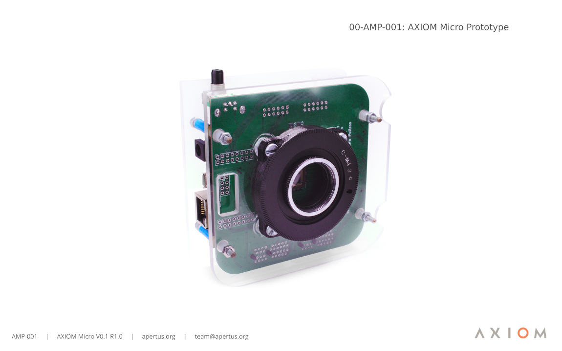
AXIOM Micro is a low-cost camera platform which allows anyone to contribute to software development and support an inexpensive, open hardware recording solution.
Whilst AXIOM Beta was being showcased at Chaos Communication Congress 2017, two bright developers from Germany became interested in the camera and decided to lay the foundations for a less costly (specifically by using a low-end image sensor), entry-level platform for software development purposes.
"AXIOM Micro uses a Xilinx Zynq FPGA SoC but this has been implemented using low-cost components. Naturally, with a budget image sensor, and when compared with the Micro's inspiration (AXIOM Beta), overall image quality is greatly reduced, however, the camera isn't intended for film-making and photography, rather, for exploring and expanding on ideas and concepts related to software or hardware that could, ultimately, be implemented into AXIOM Beta Firmare etc." - vup & anuejn.
To reduce work, most parts of the AXIOM Beta's software should be used. Only the bitstream should be a custom development as this doesn't have to be up-streamed.
- GitHub repositories.
1 Features
- AXIOM Beta compatible plugin module and shield slots.
- Less than 150€ BOM cost (see https://octopart.com/bom-tool/HYQ6fs35).
Planned changes/features for V3 hardware (currently in development):
- swappable image sensor
- ECP5 as routing FPGA, that has 5G transceivers that could (and are planned) to be used to implement USB 3.1 data transfer
- reduced functionality (no plugin modules) available without the zturn lite (the ZYNQ FPGA board) connected, so that the AXIOM Micro can be used as USB 3 webcam
2 Technical Specifications
2.1 Image Sensor
- Non-replacable 1/3" Image Sensor.
- 2.2 × 2.2 µm Pixel size.
- 12 F-Stops Dynamic range.
- ~40dB SNR.
- 2304 × 1296 pixel resolution.
- Full HD video with image stabilisation is possible!
- 60fps theoretical sensor limit.
- 12 bit RAW output.
2.2 Image Processing
- Zynq 7010 FPGA for image processing and controlling tasks.
- Onboard motion sensor.
- Onboard 4GB eMMC for firmware - the SD card slot could be used for recording.
- USB 2.0 OTG & Gigabit Ethernet.
3 Camera Structure
The AXIOM Micro uses a similar mechanical concept as the AXIOM Beta - An of the shelf FPGA development board is stacked on top of custom boards. However, the AXIOM Micro only uses one board to handle the camera's power management, image sensor interfacing and for holding the plugin modules.
It also employs the same lens-mount mounting system as the Beta (E-Mount). This allows you to use the same lens mount adapter. Some lens-mounts need thick disks to be positioned between the lens-mount and a lens-mount adapter in order to achieve the correct flange distance. For example, the micro-four-thirds mount needs to be combined with the 5mm shim.
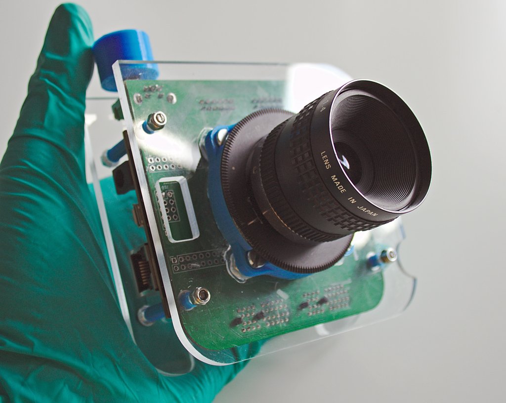
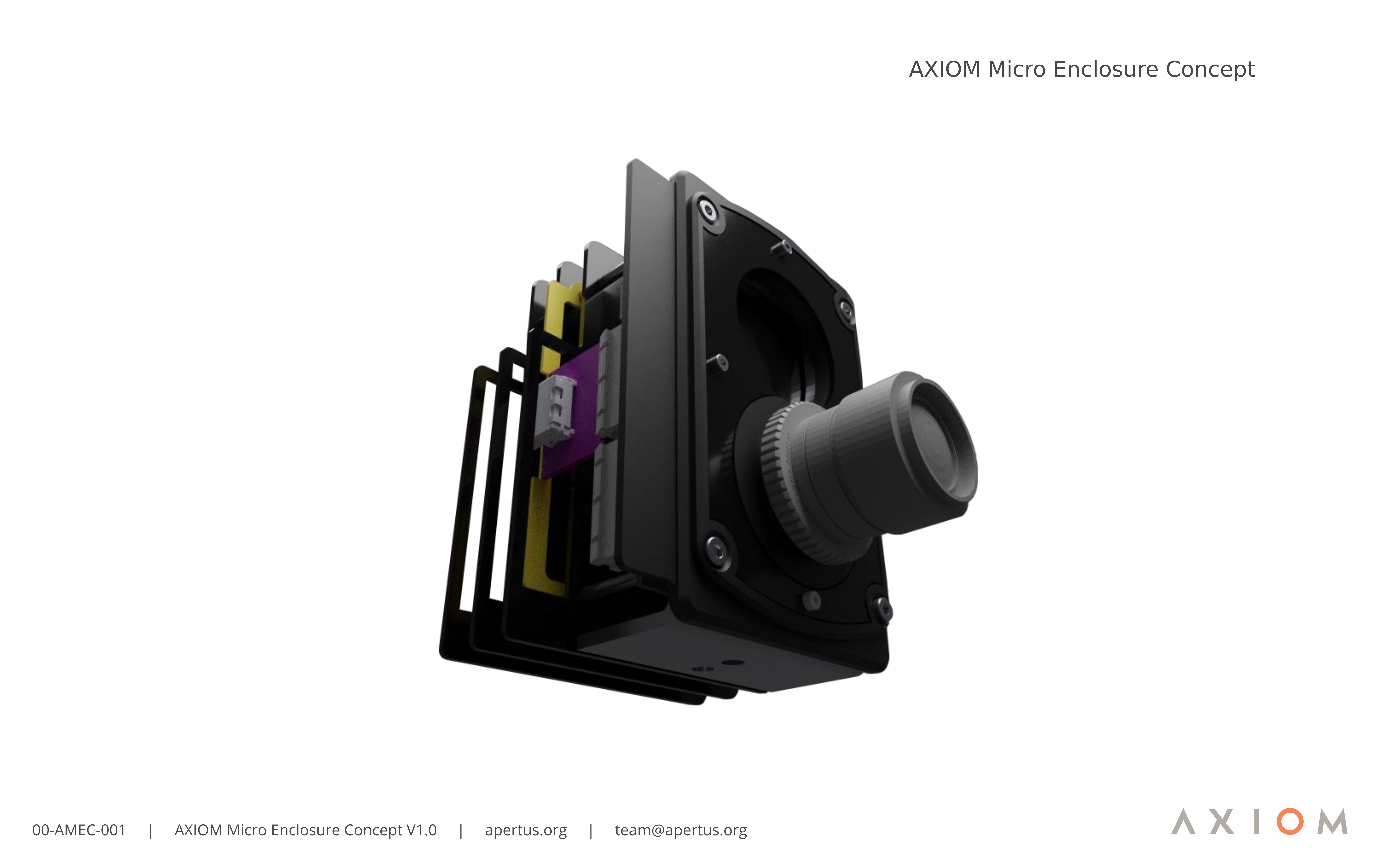
The current enclosure design for AXIOM Micro allows access to the PCB and mainly consists of cnc milled sheets of acrylic glass for the front and back side and spacers. It allows for mounting on two 15mm rig type rails. Future concepts are being considered, e.g:
CAD files can be downloaded here.
4 Development
To develop the PCBs, simply clone this repository with:
git clone --recursive https://github.com/axiom-micro/mainboard
Then use Kicad to edit the schematics and PCB.
Warning: This Project uses submodules. When you clone without --recursive Kicad won't find some libraries!
4.1 Version 2.1 Considerations / Notes
Currently there is a complete hardware redesign in progress called the AXIOM Micro R3, it's work in progress and there is no ETA. Another approach is to fix the issues and add minor modifications to the AXIOM Micro R2 and make it ready to be put in the hand of more people, this is currently called the AXIOM Micro R2.1. Below are notes and considerations for such fixes/additions:
- Currently the hardware talks HiSPI
- There are some left over GPIO, should they be routed to a header for future extension or are there specific things that should be implemented?
- Currently the header option seems more useful.
- Shield is only connected with less IO than on Beta rendering the shields incompatible, is there anything we can do about that?
- The rotary encoder is currently envisioned to be removed.
- It was considered if image sensors should be swappable which would mean putting them on a separate PCB and having mating connectors between the new PCB and the AXIOM Micro PCB.
- Considering the low cost approach of the AXIOM Micro PCB already it seems to make more sense to swap the entire board with the soldered image sensor instead of adding an additional PCB to the stack.
- What would be the different image sensors that would be of interest (super low light capabilities, higher resolution?). Maybe it would make sense to boil it down to the best 3?
- image sensors AR1335 (datasheet publicly available) and OS05A10 (datasheet not publicly available) are of interest but likely require MIPI Interface.
- Would it be possible to move the image sensor position on the PCB from the center closer to the edge of one side? This would allow bringing two cameras closer together (interocular distance) for stereo 3D applications for example.
- A few centimetres closer to the high density connector could work
- Keep IMU?


