Difference between revisions of "Beta Power Adapter Board"
From apertus wiki
m (update links) |
|||
| Line 19: | Line 19: | ||
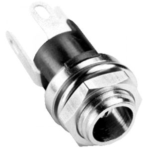
[[File:1-DC_jack4a-500x500.jpg | 300px]] | [[File:1-DC_jack4a-500x500.jpg | 300px]] | ||
Revision as of 03:36, 13 November 2018
1 About
TODO
2 Revisions
V0.2:
http://files.apertus.org/HARDWARE/AXIOM/BETA/VARIOUS/axiom_beta_power_adapter_v0.2.brd
http://files.apertus.org/HARDWARE/AXIOM/BETA/VARIOUS/axiom_beta_power_adapter_v0.2.sch
2.1 Improvement/Update Concepts
replacing AC jack with a metal one that can be screwed to the enclosure to reduce mechanical stress to the PCB


