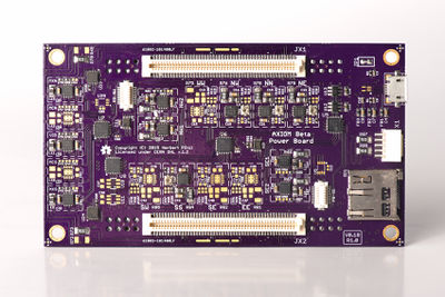
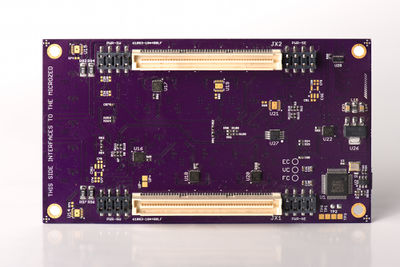
Beta Power Board
From apertus wiki
1 About
TODO
2 Planned Changes for V2
- DC barrel connector attached directly to the PB
- PICO SPOX power input connector will be moved "into" the PB so the cable can be routed inside the camera enclosure towards the backside
- RGB LED and pushbutton (ALPS SKSNLAE010 currently considered) moved from smart power adapter to PB camera orientation top/left side
3 Revisions
Current: AXIOM Beta Power Board v0.30
Archive:
axiom beta power board v0.22 test
axiom beta power board v0.17 test
axiom beta power board v0.11 test
axiom beta power board v0.8 test
axiom beta power board v0.9 test
4 Calibrating Voltages
This describes the process required when factory assembling the power board hardware in the AXIOM Beta stack.
./power_init.sh
./power_on.sh
wait a bit
./pac1720_info.sh
This will output something like:
ZED_5V          4.8828 V [1f40]         +10.1562 mV [104]   +677.08 mA
BETA_5V         4.8828 V [1f40]          +1.2891 mV [021]    +85.94 mA
HDN             3.2812 V [1500]          +0.0000 mV [000]     +0.00 mA
PCIE_N_V        3.2422 V [14c0]          +0.0000 mV [000]     +0.00 mA
HDS             3.2031 V [1480]          +0.0000 mV [000]     +0.00 mA
PCIE_S_V        3.2422 V [14c0]          +0.0000 mV [000]     +0.00 mA
RFW_V           3.2422 V [14c0]          -0.0391 mV [fff]     -2.60 mA
IOW_V           3.2617 V [14e0]          +0.0000 mV [000]     +0.00 mA
RFE_V           3.2422 V [14c0]          +0.0000 mV [000]     +0.00 mA
IOE_V           3.2812 V [1500]          +0.0000 mV [000]     +0.00 mA
VCCO_35         2.4219 V [ f80]          -0.0391 mV [fff]     -2.60 mA
VCCO_13         2.4609 V [ fc0]          +0.0000 mV [000]     +0.00 mA
PCIE_IO         2.4609 V [ fc0]          -0.0781 mV [ffe]     -5.21 mA
VCCO_34         2.4609 V [ fc0]          +0.9766 mV [019]    +65.10 mA
W_VW            2.7734 V [11c0]          +0.0000 mV [000]     +0.00 mA
N_VW            2.8125 V [1200]          +0.0000 mV [000]     +0.00 mA
N_VN            2.7734 V [11c0]          -0.0391 mV [fff]     -2.60 mA
N_VE            2.8516 V [1240]          +0.0000 mV [000]     +0.00 mA
E_VE            2.6953 V [1140]          -0.0391 mV [fff]     -2.60 mA
S_VE            2.8516 V [1240]          +0.0000 mV [000]     +0.00 mA
S_VS            2.7344 V [1180]          -0.0391 mV [fff]     -2.60 mA
S_VW            2.8516 V [1240]          -0.0781 mV [ffe]     -5.21 mA
now run:
watch -n 0.2 ./pac1720_info.sh
which will display the voltages in a clear screen and constantly update the values until you press CTRL+C
The PCB labels and the labels in the CLI correspond like the following:
WW = W_VW
NW = N_VW
NN = N_VN
NE = N_VE
SW = S_VW
SS = S_VS
SE = S_VE
EE = E_VE
Use a tiny screwdriver and adjust the trimmers on the PCB until your values look like this:
W_VW          	2.4609 V [ fc0] 	 -0.0391 mV [fff]     -2.60 mA
N_VW          	3.2422 V [14c0] 	 +0.0000 mV [000]     +0.00 mA
N_VN          	1.8750 V [ c00] 	 -0.0391 mV [fff]     -2.60 mA
N_VE          	3.2617 V [14e0] 	 +0.0000 mV [000]     +0.00 mA
E_VE          	3.2812 V [1500] 	 +0.0391 mV [001]     +2.60 mA
S_VE          	1.9922 V [ cc0] 	 +0.0000 mV [000]     +0.00 mA
S_VS          	2.9883 V [1320] 	 -0.0391 mV [fff]     -2.60 mA
S_VW          	1.9531 V [ c80] 	 -0.1172 mV [ffd]     -7.81 mA


