Ergonomics Workgroup
1 Meeting 27th of October, 2014
Are there HDMI connectors pointing away from the PCB surface they are mounted to? -> http://lab.apertus.org/T93
Lets research metal bending processes and prices.
Lets create a Grip Handle Concept and physical mock ups for testing. -> http://lab.apertus.org/T95
We need to design the stray light filter part in the AXIOM Beta as independent part from the lens mount so swapping image sensor means you do not need to swap the lens mount part as well for the matching stray light filter.
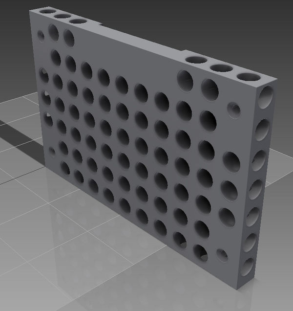
Cheese plate concepts for camera back plate and top plate (illustrations will follow).
Lets research leather (fake or fair) as material for some camera parts (hand grip, etc.)
2 Meeting 3rd of November, 2014
2.1 Researching the lens mount patent situation
Mechanical dimensions cannot be patented so anyone can build a mount that particular lenses.
Of course the manufacturer names (Sony, Canon, etc.) are trademarked so we cannot advertize any mount as "Sony E-mount" we can only call it "e-mount" or "compatible with e-mount". The word "e-mount" is very likely not trademarked.
The electronic data exchange protocol is under a Sony/Canon/etc. licenses and to acquire it you need to sign contracts and pay fees, etc. In Europe though it is not illegal to reverse engineer something if it is required for you to make specific things "work" so we will be able to listen to what the lens is saying and being told to do and would be able to create software that sends/receives "similar" commands. This is in full compliance with the law.
2.2 Camera Enclosure Surface Finish Notes
The typical options for surface finished of aluminum are sandblasting, abrasive blasting, anodizing, painting, powder coating.
The typical camera surface finish is called "Runzellack" which translates to: wrinkle paint.
Painting Aluminum is not a trivial process.
Labels can easily be CNC engraved, then painted and the wet paint wiped away, that way the paint only remains in the engraved areas and dries there.
laser engraving is another cheap way to create labels but we would need to outsource that
2.3 Manufacturing Material Notes
There are innovative wood-plastic combinations: http://www.fasal.at/ that feel similar like wood and are bio degradable. These can be used like any other injection molding raw material. The material is still in research and long term integrity, UV-resistance, etc. are unknown.
3 Meeting 10th of November, 2014
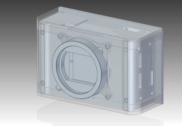
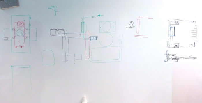
Concept to mill the enclosure out of laser cut aluminium sheets (shown here with E-mount tube) :
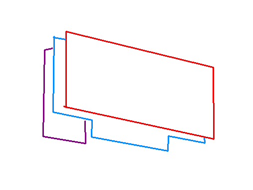
Drawing for the laser cut aluminium parts for the Beta enclosure. Raw parts for milling File:Laser cut parts.pdf
4 Meeting 17th of November, 2014
PCBs should have rounded corners to match the round corner design of the AXIOM CI and to reduce risk of injury with sharp PCB edges.
Cheeseplate backplate concept:
We will inquiry receiving samples from a powder coating service provider.
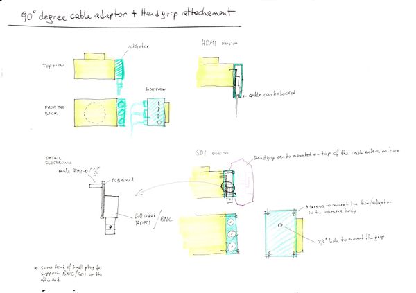
Method for getting HDMI/SDI connectors to the side/back of the camera:
AXIOM Beta Grip Handle Accessory Concept by Christoph Varga:
*comment: does not work since the soldering of usual connectors (hdmi,..) is not precise enough in positioning to make this adapter working. also there are shielding issues and every connector in between signal source and target is a loss in signal quality.
SDI needs a different 'high speed shield' wich is the left (from operators perspective) small board on the object (operator-object optical axis) side. they could be transmitted through SMA connectors which then have to get transformed to BNC somewhere outside the camerabody.
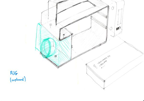
AXIOM Beta Cupboard Rig Concept by Christoph Varga:
5 Meeting 16th of Feburary, 2015
- Yolk Y2 Design ideas inspiration: http://www.designdirectory.com/yolk/Y2-digital-cinema-camera
- PE/PU foam sample touching: cardboard case as standard option, pelicase/suitcase as more expensive option to choose from, inlay foam should be the same the same, PE for bottom, PU for top, nawapur not good because of color, lack of stiffness and renewable sources are nice but where do they come from, are they organically farmed, was it fair traded? etc. too many uncertainties.
- button sample pressing/touching and evaluation
- high speed modules should be on the right camera side (seen from the camera back) or towards the back of the camera
- Mini 'DISPLAYPORT' connectors were selected as primary first module interface as there are no license issues / royalty fees compared to HDMI
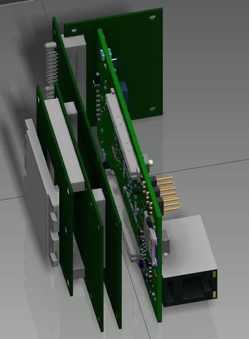
- New PCB stack concept:
6 Meeting 1st April, 2015
- Gamma: 2x smaller PCIe connectors for modules instead of one big?
- Gamma: 1x double PCIe slot to the right side of main core enclosure
- Gamma: to protect cables/connectors and allow cable routing (to the back of the camera) -> 2x protection U shaped holders at sides of Gamma modules
- Gamma: module connector adapters to allow 45° connectors as well
- AXIOM Universal Remote styrofoam concept design touching/discussion - PDF (not finished yet!)
6.1 AXIOM Remote
Regarding the wheel of the remote we could use a micro disk motor like in a DVD player. BLDC Disk motor
It has three hall sensors included and the coils can be driven to generate feedback. We can use it do adjust the friction of the wheel, increase the force at programmed positions for focus pulling or break at the end stops.
Sebastian: Herbert suggested testing a micro stepper if we want to go in that force feedback direction. It might be an overkill for the very first version of the remote. Problem with any force feedback solution though is that they are quite power hungry (can be switched off of course).
7 Meeting 13th of July, 2015
New Simple Enclosure Concept:
- solid skeleton as core
- skin: 5 sided box (one bend piece) attach from front
- solid backside lid (screw to skeleton) - leave out module slots
- rubber edge/corner connector
- 1.5mm steel (2.5x cheaper than aluminum)
- tripod threads cut to skeleton base/top
- no lip at back
- cooling fan inside at top
- mount point behind top fan?
8 Nov, 2017
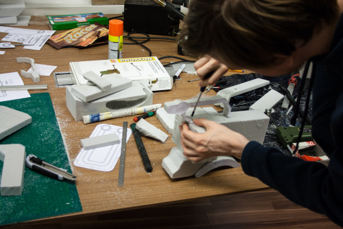
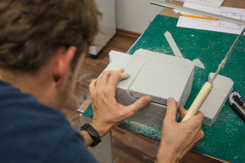
We did a mini ergonomics workgroup meet up to build two camera models out of styrofoam to evaluate general size and handling of concepts we only had as 3D CAD models before.
9 Notes for next meeting
please add them here
