Difference between revisions of "00-Printed Circuit Boards"
| Line 19: | Line 19: | ||
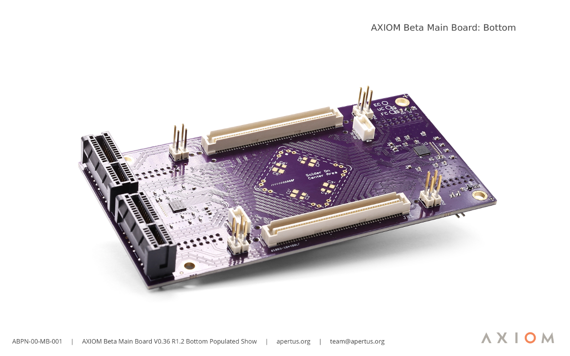
The Beta Main Board | The Beta Main Board is the camera's equivalent of a PC's motherboard. It hosts two external medium-speed shield connectors and two high-speed plugin module slot connectors - These act as a central switch for defining where the data that's captured by the sensor and other interfaces gets routed to inside the hardware. In this regard, all specifics can be dynamically reconfigured in software. | ||
BOMs and Schematics of all AXIOM Beta Power Boards - https://wiki.apertus.org/index.php/Beta_Main_Board | BOMs and Schematics of all AXIOM Beta Power Boards - https://wiki.apertus.org/index.php/Beta_Main_Board | ||
Revision as of 03:55, 20 February 2019
1 00-SB: Sensor Boards
The Beta CMV12K ZIF Sensor Board hosts the heart of every cinema camera - the (CMOS) image sensor. apertus° offered three different sensor options during the crowd funding campaign; Super35, Super16 and 4/3rds, and as almost 90% of the backers opted for the Super35 sensor its respective module was developed first. The camera uses the ams Sensors Belgium CMV12000.
2 00-MB: Main Boards
The Beta Main Board is the camera's equivalent of a PC's motherboard. It hosts two external medium-speed shield connectors and two high-speed plugin module slot connectors - These act as a central switch for defining where the data that's captured by the sensor and other interfaces gets routed to inside the hardware. In this regard, all specifics can be dynamically reconfigured in software.
BOMs and Schematics of all AXIOM Beta Power Boards - https://wiki.apertus.org/index.php/Beta_Main_Board
3 00-PB: Power Boards
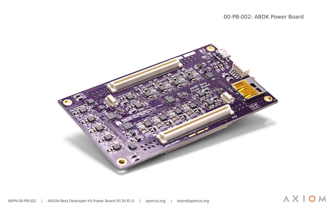
The AXIOM Beta Power Board PCB generates all the different supply voltages for the chips and logic on the other PCB’s inside the camera. It also monitors currents so that it can estimate remaining power based on the recorded consumption. In the current revision of the camera a predefined set of supply voltages matching the current application with the rest of the camera have been generated, in the future however, it will be possible for users to dynamically reconfigure voltages according to their needs through the camera’s software.
BOMs and Schematics of all AXIOM Beta Power Boards - https://wiki.apertus.org/index.php/Beta_Power_Board
3.1 00-SB-001-0V16-1R2c
- 00-SB-002-0V16-1R3c
- 00-SB-003-1V2-1R2
- 00-SiB-001-0V12-1R0
- 00-DS-001-0V1-1R0
- 00-MB-001-0V36-1R2
- 00-CSO-001-
- 00-SPMOD-001-0V1-1R0
- 00-SPMOD-002-0V1-1R1
- 00-TPMOD-001-1V2-1R0
- 00-TPMOD-002-1V2-1R1
- 00-SHDMI-001-0V2
- 00-SHDMI-002-0V4
- 00-SHDMI-003-0V5
- 00-SHDMI-004-0V6
- 00-SHDMI-005-0V8-1R2
- 00-PMODD-001-1V0


