AXIOM Beta/Developers
Preamble
This guide includes details for developers, such as setting up a development environment for camera FPGA development and building and testing firmware images.
1 Remote Access
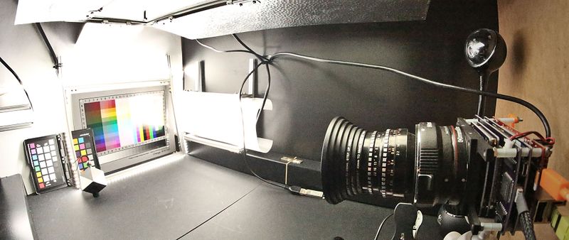
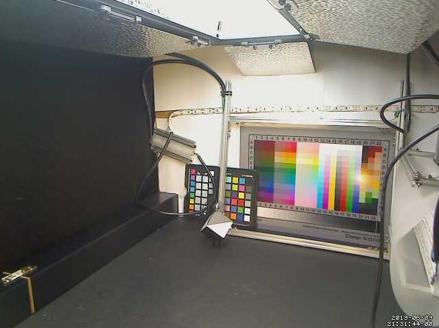
For developers and people interested in testing certain aspects of the AXIOM Beta we provide remote access to an AXIOM Beta test-camera inside a controlled dark-box. This can be performed 24/7. The dark box is located in our AXIOM office and also allows you to turn on/off several light sources remotely.
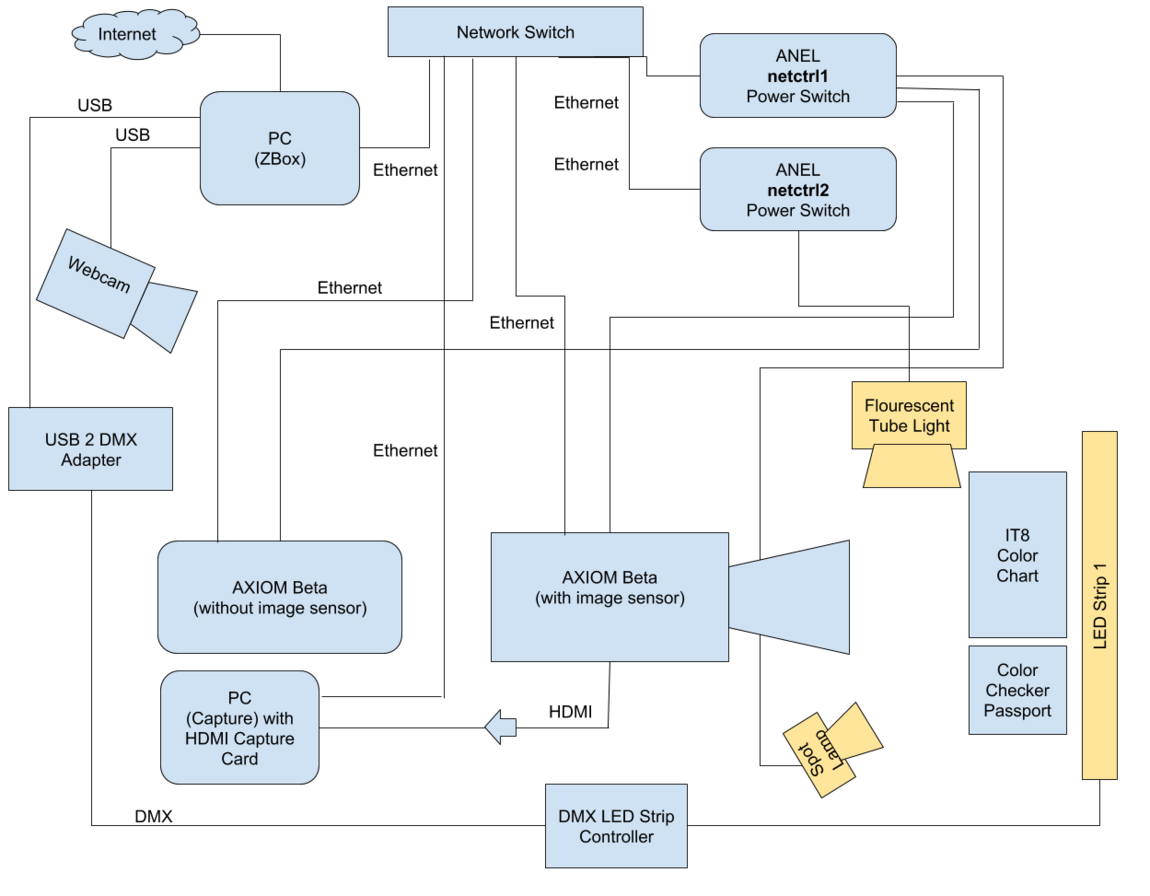
The set-up is configured as follows:
1.1 Connecting to ZBox
The Zbox is a small PC at the AXIOM office that can be accessed remotely by developers and GSoC students to work on AXIOM Beta hardware at the office. There are a few peripheral devices as well.
Hostname: remote.apertus.org
Port: <you-know-the-port>
Access is granted to <username> via SSH key only.
1.2 Anel NET-PwrCtrl Power Switch
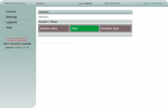
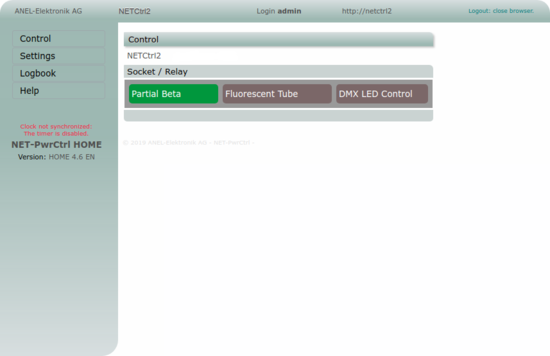
The Anel NET-PwrCtrl Power Switch provides power sockets which can be controlled remotely through a web interface. This allows turning on/off the AXIOM Betas in case they hang due to a software error, etc. or to control lights that illuminate the test chart the AXIOM Beta is filming.
Note: Please switch any lighting off after you are done.
1.2.1 Access
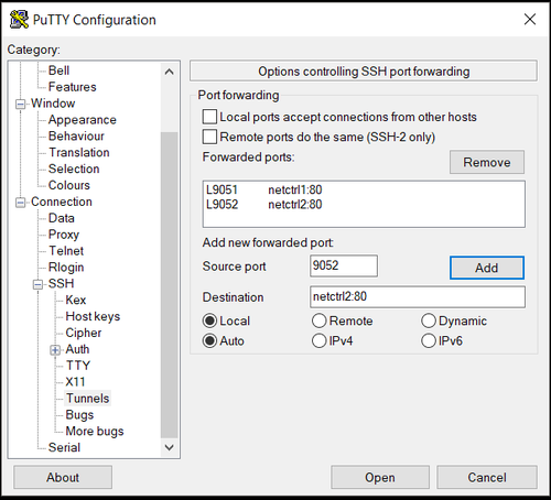
Tunnel the following ports through SSH:
Local 9051 to netctrl1:80
Local 9052 to netctrl2:80
Example: ssh -p <remote_port> <user>@remote.apertus.org -L <local_port>:netctrl2:80
Once the SSH Tunnel has been established you can go to localhost:9051 and localhost:9052 in your browser and should be able to access the ANEL WebGUI.
1.2.2 Sockets
Netctrl1
Socket 1: AXIOM Beta (with image sensor)
Socket 2: Zbox
Socket 3: Darkbox Spot (lamp)
Netctrl2:
Socket 1: Partial Beta (without sensor)
Socket 2: Flourescent Tube Light
Socket 3: DMX LED Strip Controller
Credentials are not listed here but can be provided on request.
1.3 AXIOM Beta (with image sensor)
SSH: ssh operator@beta_a
Copy files from camera to ZBOX: scp <user@host>:<remote path> <local path> -> scp operator@beta_a:/opt/test_snap.jpg ./
1.4 Webcam
There is a small webcam installed that films the inside of the dark box remote setup. This webcam is connected to the ZBox and with the Linux software “motion” streams live snapshots to the ZBox localhost:8081. If you want to view the webcam you need to create an SSH tunnel.
Address: localhost:8081
Example: ssh -p <remote_port> <user>@remote.apertus.org -L <local_port>:localhost:8081
1.5 DMX Light Control
The LED strips are made by waveform lighting: FilmGrade™ Daylight (6500K) / 12V 95+ CRI.
The ZBox has a 5-channel DMX controller with white LED strips attached, running at 30KHz PWM.
Each channel can be set from 8 (lowest visible value) to 255 (maximum brightness). Values lower than 8 will turn off the LEDs.
Make sure the olad service is running:
service olad start
Lowest dim level:
Lowest dim level is 8.
ola_set_dmx -u 0 -d 8,8,8,8,8
Full on:
ola_set_dmx -u 0 -d 255,255,255,255,255
Full off:
ola_set_dmx -u 0 -d 0,0,0,0,0
Channels:
Channels are represented by each dim level setting number after ola_set_dmx -u 0 -d
- Channel 0: Short LED strip with diffuser.
- Channel 1: Currently empty.
- Channel 2: Back light with diffuser.
- Channel 3: Long LED Strip plus LED frame.
- Channel 4: Currently empty
Diagnostic:
  ola_dev_info
  ...
  Device 10: DMXking.com - ultraDMX Micro, Serial #: 84003036, firmware 1.44
  port 0, IN, priority 100
  port 0, OUT, patched to universe 0
If the output port is not "patched" (whatever that means), run:
ola_patch --patch --device 10 --port 0 --universe 0
1.6 Temperature Sensors
in the directiory:
/usr/local/script/
there is a script:
./temper.sh
that reports the temperature in the remote dark box at the top and at the bottom of the box (there is 24/7 air ventilation in the box):
usb-0000:00:14.0-3      28.12 °C
usb-0000:00:14.0-5.4.2  27.75 °C
1.7 HDMI Capture
The "capture" PC receives the HDMI signal from the AXIOM Beta through a black magic decklink 4k mini recorder PCIe card.
https://www.blackmagicdesign.com/products/decklink/techspecs/W-DLK-33
The following commandline tools are available:
CaptureStills
Capture
DeviceConfigure
more in:
/home/axiom/src/blackmagic/sdk/Linux/Samples/
1.7.1 Preview (X11 forwarding)
By connecting to the capture PC by using -X or -Y parameter for SSH, it's possible to see the live video stream by using following command:
gst-launch-1.0 decklinkvideosrc mode=10 connection=hdmi video-format=4 ! autovideoconvert ! xvimagesink
2 Gateware
One of the major components of the Axiom-Beta Firmware is the FPGA gateware for the Zynq Programmable logic (PL). The Bitstreams are currently not build in the CI due to the requirement of proprietary software.
2.1 Setup Development Environment
The camera gateware is developed using Xilinx Vivado Design Suite. To setup a development environment where you can modify FPGA related code and build a bitstream, do the following:
1. Download and install Vivado. You can install a trial version that is good for 30 days but is otherwise unrestricted and will allow you to build the bitstream. After that you can purchase a license, or use the WebPACK version for free, which is completely sufficient for the fpga used in the AXIOM Beta. If you have purchased a Zedboard you may be eligible to receive a license included with your purchase.
2. Download the MicroZed Vivado board definition files. Extract the zip file and put the files in your Vivado installation directory ~data\boards\board_files.
3. Clone the beta git repo.
4. If necessary, you may need to update the BOARD_PART property in the build script of your cloned firmware repo vivado.tcl to match the version of your board definition files. To view of a list of valid board_parts you can enter the command get_board_parts in the Vivado Tcl Console. Make sure you have put the above board part files in the proper directory and the version board version is correct.
2.2 Building Gateware
The actual beta FPGA gateware for the zynq pl is located under peripherals/soc_main, and is built using the Vivado build script vivado.tcl in that directory.
To build the gateware (in directory where you checked out axiom-beta-firmware):
1. [axiom-beta-firmware] $ cd peripherals/soc_main
2. [soc_main] $ mkdir build && cd build
3. [build] $ vivado -source ../vivado.tcl (assuming vivado is in your PATH, on Linux it is normally installed under /tools/Xilinx/Vivado/<version>/bin/vivado)
Vivado should launch the GUI and begin building the source files. If successful, you should end up with a cmv_hdmi3.bit in your build directory. This is the actual fpga bitstream and can be copied to the camera directly for testing.
2.3 Testing Gateware
2.3.1 On Camera Hardware
Bitstream files are normally installed to /opt/BITS on the camera. A symlink in the camera root user's home directory controls which bit is loaded to the FPGA on startup. The easyest way to load the new bitstream is to reboot the whole device. To test a built bitstream on camera hardware, do the following:
1. Transfer the firmware bit file to the camera. (in your build directory):
$ scp ./cmv_hdmi3.bit root@beta:/opt/BITS/cmv_hdmi3-test.bit
2. Delete the existing symlink and link to your new bitstream. (on the camera):
~$ rm -f cmv_hdmi3.bit && ln -s /opt/BITS/cmv_hdmi3-test.bit ./cmv_hdmi3.bit
3. Reboot the camera:
~$ sync && reboot now
If all goes well the camera should reboot and load your new development FPGA gateware.
2.4 Custom HDMI Output Modes
The Axiom Beta currently supports a few different HDMI output video modes, namely 1080P60 and 1080P50. You may need to add a new mode to support your HDMI display or recording device. The general process is as follows:
1. Find out the mode timing parameters of your display device and the output mode you want to support. This can be done by looking up your device in the [EDID database http://edid.tv/edid/469/]. Try to get as much information as possible, you are looking for detailed timing information that includes the pixel clock frequency, blanking, horizontal/vertical offsets, etc. You can also dump EDID information by connecting the device to your laptop or PC and running a edid dump command. Another good way is to use a raspberry pi and dump the parameters using the commands tvservice and edidparser. This also allows you the benefit of testing modes via the raspberry pi to make sure they are correct before trying to get them working on axiom beta.
2. Create a new, empty Vivado project for the MicroZed Board (do not add any source files), and open the IP Integrator section.
3. Add a clocking wizard and auto-configure the pins.
4. Double-click on the clocking wizard to show the configuration and under the Output Clocks tab, enter the desired frequency of your video mode's pixel clock multiplied by 5. For example, if your clock is 146 MHz, specify 730 MHz.
5. Note the parameters under MMCM Settings.
6. In your checked out copy of axiom-beta-firmware, open the file peripherals/soc_main/hdmi_pll.vhd.
7. Add a new HDMI clock timings mode under hdmi_config_a. Three clocks need to be specified, one for the pixel data clock, a tmds clock, and the actual hdmi clock. The tmds_clk needs to be the pixel clock multiplied by 5 as found from the parameters above. The other two clocks can be divided by 5 or another number to get the desired pixel clock (based on the value of DIVCLK_DIVIDE). Look at the other HDMI clock configuration items for some examples.
As an example, here is a clock config for a 146 MHz pixel clock:
HDMI_146MHZ => (
    CLKIN1_PERIOD => 10.000,
    CLKFBOUT_MULT_F => 36.500,
    DIVCLK_DIVIDE => 5,
    --
    CLKOUT0_DIVIDE_F => 1.0,
    CLKOUT1_DIVIDE => 5,
    CLKOUT2_DIVIDE => 5,
    --
    CLKOUT0_PHASE => 0.0,
    CLKOUT1_PHASE => 0.0,
    CLKOUT2_PHASE => 0.0
)
This equates to a 146 MHz pixel clock and 730 MHz tmds clock.
