AXIOM Remote/Hardware
1 Printed Circuit Boards
2 Todo
- add screw on lower left side:
2.1 PCB Version 0.9
The first development prototype of the AXIOM Remote printed circuit board (V0.9) has been designed and routed, ordered, received and populated. This first version is not meant to be perfect (for testing we just used a simple 6x6mm Alps push-button type - not the more expensive ones with better haptic feedback) but should provide a good foundation for developers to focus on ensuring that the menus work and how to create an intuitive and pleasant user experience when operating an AXIOM camera.
PCB Source files: [1]
2.2 Version 2 Prototype
Plans/Considerations:
- Switch to ATSAME70Q21 MCU (exact model?)
- Remove Second Knob (For menu navigation and the changing of parameters so far we found no use for it designing the UI).
- Light guide for "status" and "operation" indicators
- Light guide also as button illumination possible? maybe https://octopart.com/slp3-150-100-f-bivar-2289195?r=sp&s=KfHCVMw1QUq1RdKjDDNtJA - turns out this is a rather complex topic - skip button illumination for next revision?
- In the future we may add flash memory for storing of images - for version 2 we left it out. So far we have not exceeded the PIC32MZs internal storage memory but if we want to make the internal help system more extensive with lots of added illustrations/images it might be required to add more flash storage. Routing looks challenging for a 2 layer PCB... consider dropping it again for now.
- Remove left side rocker switches. So far we have not found any function for them. They are prone to being switched accidentally as they stand out from the device quite far. Having buttons/switches on the left side of the remote prevents it from being attached to the camera/rig on that side.
- Remove top side pushbuttons. So far we have not found a real application for them. In line with good user interface design / user experience these buttons need labels so the user clearly sees what is going to happen when he/she presses them. This is difficult as the label would not be visible from the front of the device.
- Reduce number of RGB LEDs to two (for status LEDs: State and Operation). So far we have not discovered any real world benefit to having RGB LEDs to illuminate pushbuttons. Changing the button illumination color to indicate something happening while pushing it makes little sense as while pushing it the users finger is covering the button making it impossible for the user to see it.
- Having one white LED per pushbutton could make sense that as it could indicate which buttons are currently active (requires buttons to show significant transparent surface so the light can shine through). We will see if we have enough lanes/space for that or revert to using one white LED for multiple buttons illumination.
- add 4 more holes to PCB somewhere close to eachs PCBs corners so the enclosure back can be screwed together with the enclosure front.
- to save space some cutouts on the PCB would be handy for adding thread mount points to the enclosure in the middle of each side
- shall we add additional PCB screw holes near the push buttons to add additional stability and prevent the PCB from being bent by force being applied to push buttons. Screw holes take away quite a big amount of routing space so the goal is rather to add support pillars without screws from the enclosure back where the pcb could be prone to bending due to buttons being pushed.
- replace slide switches for ON/OFF and LOCK with pushbuttons
- decide on hardware vs software vs combination of the two: button de-bouncing
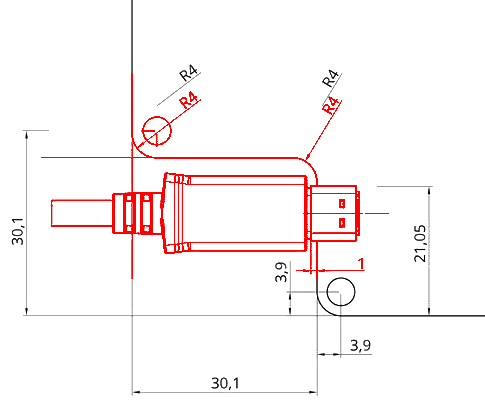
button placement and PCB dimensions drawing:
.jpg)
PCB:


Enclosure CAD Design << Work in progress.


Concept October 2019
3 Electronic Components
- Core Processor: A PIC32MZ was chosen. Two additional smaller PIC16 are used for handling push button, rotary encoder and LED IO.
- LED driver chips: STP08DP05, CAT4016HV6, PCA9957HNMP
- Display: A 2.8" 320x240 TFT from Adafruit ([2]) which is pin compatible with https://www.buydisplay.com/default/serial-spi-2-8-tft-lcd-module-display-320x240-optional-touch-screen was chosen. Higher resolution and more complex device like iphone 4 replacement display (326 PPI 3.5" 960×640 px) or http://www.ebay.com/itm/OEM-HTC-Droid-DNA-ADR6435-Original-LCD-Screen-Display-Repair-Replacement-Parts-/350711245261 smaller bezel )(documentation through: https://hackaday.io/project/364-mipi-dsi-display-shieldhdmi-adapter) were considered but not used to reduce complexity.
- USB-C Connector: https://www.mouser.at/ProductDetail/Molex/105450-0101?qs=%2Fha2pyFaduhF3W5Py2vKQTba%2FILJ1L3I7J43fQzUcJRh4CXgYxqqmg%3D%3D
- 3D accelerometer to measure device orientation was considered but not implemented - there is really only one orientation that the Remote is designed for.
- AXIOM Remote is currently powered externally via 5V DC supply (internal batteries might be considered for the future: 4x AA battery tray -> cumbersome - lithium ion battery pack that is integrated into the remote and is automatically charged through 5V/camera would be preferred)
- currently the firmware is programmed with a PICkit2 directly into the PIC32MZ flash memory - in the future this shall be done over USB - having a separate microSD card containing the devices firmware is not planned.
- The AXIOM Remote has no requirement for internal RTC (plus button cell battery) - instead timecode is synced with/by a connected AXIOM Beta.
Connectivity:
As we do not want to require a custom cable or a custom connector-cable assembly we try to stick with established standards that are able to transfer data (shielded) and power over the same cable
We considered:
- Hirose HR10A-7P-4S (a bit expensive and massive) - requires custom cable assembly
- 4 pin 2.5 or 3.5mm audio cables - problem is that audio cables are not designed to provide power
- USB - seems to be the most widely available off the shelf solution for this requirement
To reduce the stress of leverage forces on connectors and the PCB we opted for the idea to use an panel mountable part or USB extension cable (panel mount extension cable) that is plugged into a USB connector on the PCB (SMT if possible). To keep the required area small we will try to find a solution that uses USB-C or if that does not work a USB Mini B connector.
3.1 Rotary Encoders
The optimal number of detents seems to be between 20-30. 20 detents is pretty standard, 30 is not as widely used but still mostly available. We want a 14/15mm metal D-type shaft rotary encoder with push-button functionality.
CTS 290VAA5F201B2 is the current favourite, short 15mm shaft, it does not have a thread and nut for mechanical mounting but the click operation is close to silent, which no other candidate has from the samples evaluated so far: https://www.digikey.at/product-detail/en/cts-electrocomponents/290VAA5F201B2/CT3011-ND/639659
Considered: ALPS SRBE210200 low profile rotary encoder + push switch (only 12 detents though)
EM11B16140AE 15mm shaft, magnetic encoder, 16 detents, 20+€ very expensive.
Bourns PEC11L - 15mm shaft, 24 detents 1-2€ / pc - PEC11R - 4 2 15 F - S 0024
https://octopart.com/en12-hn22af18-bi+technologies-7730374
EN11-HSM1AF15
https://uk.rs-online.com/web/p/mechanical-rotary-encoders/6234316/
http://www.potentiometer-encoder.com/Encoder/11MM_Encoder/EC11-1S-D5*4.5-L12KBSMT
https://www.jsumo.com/bourns-rotary-encoder-smd-15-cpr
Turning Knobs:
All aluminium, 30-35mm outer diameter, 15-16mm height, knurled outer surface:
on aliexpress:
/item/32813571235.html
/item/32815026029.html
https://www.amazon.co.uk/Speaker-Knobs-TOOGOO-35x16x6mm-Aluminum/dp/B01H01M4XC
3.2 Buttons
We evaluated several buttons for their haptic characteristics:

ALPS SKSTAAE010 (grey color code in picture above).
Marquardt 3006.2100 (blue color code in picture above) - costs 3+€ per piece though with integrated white illumination. orange/yellow illumination is much cheaper ~1€/pc: https://octopart.com/search?q=3006%20marquardt&sort=median_price_1000&sort-dir=asc
ALPS SKPRAAE010 (black color code in picture above)
In the AXIOM Remote V2 hardware we want to test:
- Marquardt 3006 - 4N operating force - 1mm travel - https://www.marquardt-switches.com/tact-and-key-switches.html?&no_cache=1&tx_produktkatalog2_pi1%5Bmode%5D=overview&tx_produktkatalog2_pi1%5Bmodifier%5D=0&tx_produktkatalog2_pi1%5Bvalue%5D=3006
- Diptronics ML4L12WQR - 1.56N operating force - 0.25mm travel - https://www.tme.eu/Document/f5bcaf9e5a8c14fcfd95660dcf9853dc/ML4_SERIES_DTE.pdf
3.3 Extension Port
The extension port allows adding additional devices to the AXIOM Remote, this could be a wireless module, battery pack or additional dials and controls.
It utilizes a samtec IPT1-105-01-L-D-RA connector with two connectors of 2x5 pin banks each. The mating connector is called IPS1-105-01-L-D-RA.
The purpose of the connector is to provide power and data transfer to and from an extension module.
The Samtec connector is meant to be flush with the outside enclosure surface which means it extends 1.1mm beyond the PCB.

