Liteplacer PnP Machine Notes
We bought a liteplacer kit from http://www.liteplacer.com/
Here are some observations and improvements we came up with here and there.
1 Axis Setup (Liteplacer/OpenPnP)
I found these values to be most accurate:
X-Axis Travel per Revoluion ($1tr): 39.983mm
Y-Axis Travel per Revoluion ($2tr): 39.853mm
2 Eagle Component Export ULPs
To export component locations/orientation, etc from Eagle to liteplacer we modified the existing ULP a bit to also support the bottom PCB components: File:Liteplacer eagle ulp.zip
3 Liteplacer Control/Electronics Enclosure
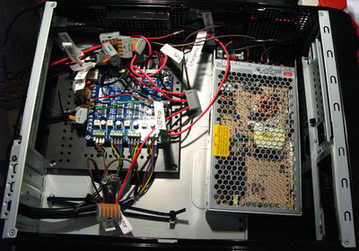
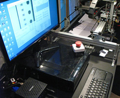
We selected a MiniITX desktop PC enclosure to contain the liteplacers control electronics (TinyG and Meanwell 24V DC power supply): http://www.lc-power.com/en/product/gehaeuse/mini-itx/lc-1400mi/ We removed all the innards (power supply, cables, 3.5" disk cage) from the pc enclosure. To attach the Tinyg PCB to the enclosure we designed a custom part and CNC milled it from a sheet of epoxy paper laminate we still had lying around: https://cad.onshape.com/documents/9df1eefffb6ba602cab7476d/w/11e83d0542bfd37a98dc8e84/e/6e4a5ea849f3278b360d4aee
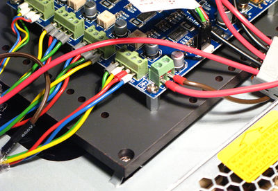
With 4x M4 hex spacers and screws we attached the TinyG to the plate and standard screws (same ones used to attach MiniITX mainboards) to the enclosure. The many holes spread around the board outline are meant for cable ties as it was unclear first where the cables from the motors, sensors, and lights would be mechanically attached exactly.
4 Bottom Vision Settings
Liteplacer originally used thin needles to pick up parts which bend quite easily. The software is designed to measure this bend offset and automatically correct it. The liteplacer kit switched to using Samsung nozzles this summer which almost completely solves the offset issue. The software is still able to calibrate the nozzle tip offset for even more accurate placements though (fractions of a millimeter) but the documentation is a bit sparse. So we help change that :)
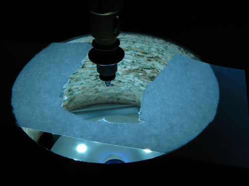
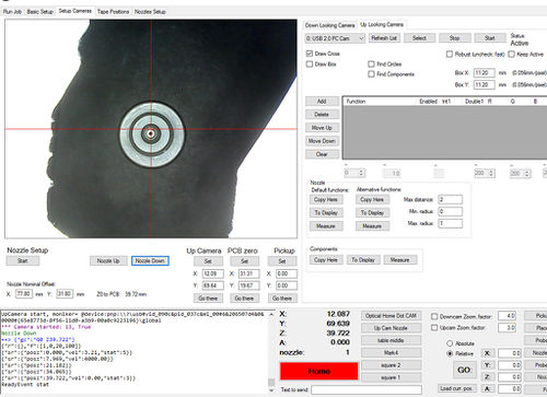
The first issue to solve is the cameras autobrightness behaviour is always too bright: the nozzle is black, the nozzle shade is black, the camera turns up brightness too far.
We solved this issue by placing white sticky labels onto the table covering the bottom vision cameras view partly (of course you leave the center area free for the nozzle). The white area in the cameras view gets it to tune down brightness so it can actually see the nozzle properly:
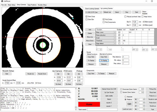
Vision parameters for the smallest nozzle with 0.225mm hole radius:
5 Cable Chains Stability Fix
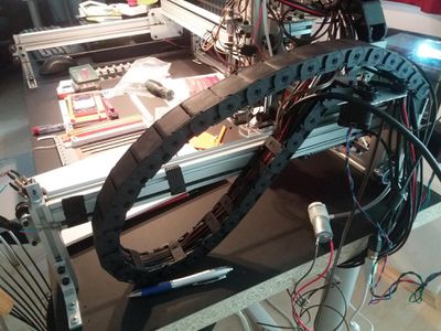
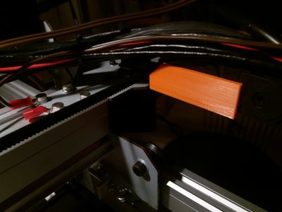
Once the cable chains have been filled with all the cables going to the head the weight can lead to the first element of the chain giving way.
Solution:
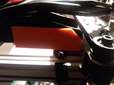
We created a small 3d printable piece to put between the cable chain and the sheet metal to act as support structure for this first cable link element. To make this element strong and riggid we recommend 3d printing it with high fill rate (we used 70%).
Download: File:Liteplacer cable chain bracket support.zip
6 Grounding the Machine
The official liteplacer assembly guide does not go into much detail when it comes to ESD and grounding the liteplacer machine parts: http://www.liteplacer.com/select-a-table/ There are sliding parts moving on rubber wheels so ESD needs to be dealt with.
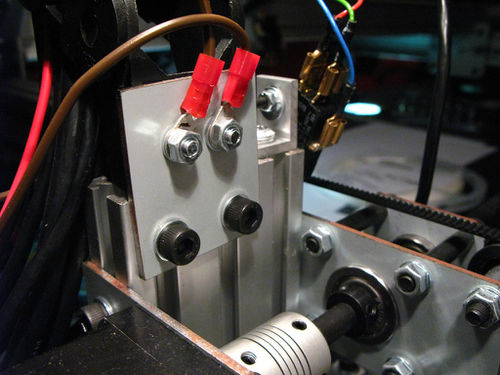
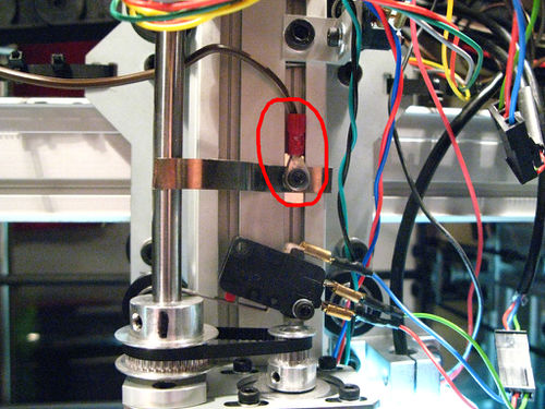
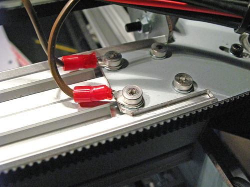
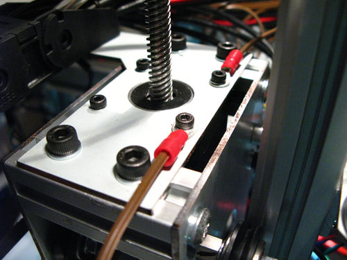
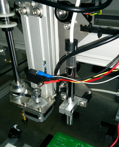
We came up with a way of connecting together and grounding all metal parts of the liteplacer with 4mm cable eyelets.
When selecting which screws to use the eyelets with consider that aluminum is only conductive if the screw cuts directly into the metal. First we considered drilling additional holes and cutting threads but ended up finding existing screws in all required locations. Please note that you normally choose green/yellow cables for grounding but our favorite hardware store had only brown ones at the time of purchasing these.
7 Camera Replacements
The default cameras the Liteplacer ships with are 640x480 no name USB 2 cameras and they show quite regular USB disconnects. With out glossy OSHPark PCBs the dynamic range of the image sensors is already overburdened and the result is clipping and not seeing anything on the PCB anymore.
7.1 Top Vision Replacement
After reading around and asking other community members we decided to go with:
- Andonstar 2 Mp Microscope USB camera for 46 € from ebay: http://www.ebay.de/itm/231925914354
- SHAT1220 to hold the camera http://uk.misumi-ec.com/vona2/detail/110300013940/?HissuCode=SHAT1220&PNSearch=SHAT1220&searchFlow=results2products&Keyword=SHAT1220
This camera has a better image sensor, better dynamic range with higher resolution and you can manually set the focus. Also with the long tube you can decide how close to the PCB surface you want to place the camera so you get a magnification level that you choose.
Keep in mind that you need an USB extension cable to use this camera.
There is a known issue with the cable wobbling at the top end of the camera so Malte Randt (http://malte-randt.de) created a 3d printable cable clip: Andonstar_cable_clip_v2.zip
7.2 Bottom Vision Replacement
We got the Logitech C270 USB HD Webcam plus the custom camera holder 3d print parts and hexagonal LED rings by http://malte-randt.de/3d-printable-camera-mount-for-liteplacer-pp-machine/
Note that you need to dissassemble the Logitech webcam, unsolder the LED and microphone and cut open the drop of glue on the lens tube so you can change the focus for closer focus distances.
Also note that this camera/LED ring assembly requires a bigger hole in the liteplacer table.
8 OpenPnP
As the liteplacer software can currently not utilize the bottom vision camera for measuring component offset the general suggestion is to use OpenPnP software with the liteplacer hardware.
Instructions collected from various places (like http://liteplacer.com/phpBB/viewtopic.php?f=13&t=308):
Preparations:
- physically swapping zmin and zmax limit switch wires on the tinyg is still required to use openpnp
This was tested with Tinyg:
[fb]  firmware build            440.20
[fv]  firmware version            0.97
Startup:
Use the GCode Driver, not the TinyG driver.
All machine relevant settings (and drivers configurations) for OpenPnP are stored in machine.xml in this location: https://github.com/openpnp/openpnp/wiki/FAQ#user-content-where-are-configuration-and-log-files-located.
This File:Machine.zip is meant to be tailored to the Liteplacer.
- nozzle-camera offset (https://github.com/openpnp/openpnp/wiki/Setup-and-Calibration%3A-Nozzle-Setup#user-content-head-offsets) should be in the range of X:-77.6mm Y:-31.8mm
- top camera units per pixel should be in the range of 0.082
Follow the official OpenPnP manual for setup and calibration: https://github.com/openpnp/openpnp/wiki/Setup-and-Calibration.
8.1 Visual Homing
OpenPnP can do visual homing as described here: https://github.com/openpnp/openpnp/wiki/GcodeDriver#user-content-visual-homing
Print out the image (on the right) on a sticky label or use doubled sided glue tape so that the white circle is around 1mm in diameter. As the liteplacers default cameras do auto exposure place enough white area around the home-fiducial so that the black really becomes black.
Tests have shown that smaller fiducial circles (around 1mm diameter) have led to more accurate results than larger ones (2-3mm)
Currently OpenPnP requires a white dot on black background on the tables desired origin position. The size/shape can be altered in OpenPnp, the colors can't. A new downlooking camera vision pipeline system (similar to the bottom vision pipeline system currently in place) is currently in development and will also replace the optical homing setup.
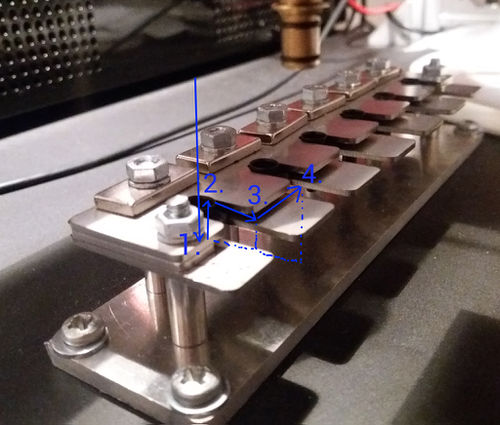
8.2 Nozzle Tip Changer
The liteplacer software can define separate moves for loading and unloading each nozzle tip. In OpenPnP only one set of motions can be defined per nozzle tip and the unloading procedure is executing the loading move in reverse. This is not optimal but works if some extra care is applied to make sure the moves work flawlessly in reverse. Here is a motion setup which seems to be working fine so far:
