PCB Component Footprint Validation Procedure
From apertus wiki
This procedure is to ensure PCB components fit inside their allotted space, it also checks whether connections from the components schematic are routed correctly electronic board designs.
1 Preparations
- Install Eagle Freeware edition: http://www.cadsoftusa.com/download-eagle/ and choose "Freeware license" when running it for the first time. (OSX Experience: you need to start it twice in freeware mode)
- Download *.brd,*.sch and library archive of a project PCB
- Open the *.brd or *.sch file in Eagle and go to File -> Export -> Partlist
- Save the partlist as text file and add it to the wiki page of that PCB
2 Verification
2.1 Footprint validation
- The saved partlist contains several columns, the "device" and "library" are the most important. (note: "0402" components are standard SMD parts and the footprint will likely be just fine, more important are the non standard parts)
- Pick a line from the partlist and use a search engine to find a datasheet of the "device" matching the entire partnumber.
- Most of the time either the manufacturers website or the distributors (farnell, RS, digikey, mouser) will offer them for download.
- Add the partnumber and datasheet URL to the partlist table
- Each part in the part list has a library name, we can open this library in Eagle.
- Extract the "libraries archive" from the files section to a local directory where you can access it with Eagle.
- In Eagle go to Library -> Open and select the matching library from the extracted files that you want to inspect.
- Once the library window opened go to Library -> Package and choose the one matching the devicename in the partlist
3 The actual checks
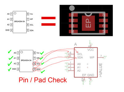
- Each used part in the library must be validated against the original dataset
- Check if the pitch & position of all pads matches the specifications in the datasheet
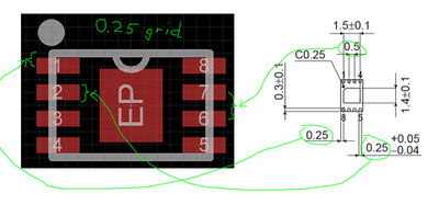
- For through-hole parts check if all pins are fully surrounded by pads (green) - SMD components have red SMD pads
- check if the pin numbering/naming (under "Device") is matching the datasheet


4 Component Selection
- for parts that have no value defined yet check the recommendations and research matching parts
- For guidance on part selection specifics ask Bertl on IRC. (optimally provide him with PCB version/revision identification and partlist numbers so he knows exactly what you are talking about)
- search for alternative equivalent parts
- help us find the best price from mouser, digikey, farnell, RS, etc.