Sandbox
1 Buttons
{{#if:
| | [[Parameter target is empty!|
}}
2 Header 1
2.1 Header 2
2.1.1 Header 3
2.1.1.1 Header 4
2.1.1.1.1 Header 5
Vivamus accumsan mauris eget orci vehicula, et tristique metus cursus. Vestibulum at tristique arcu, eu dignissim massa. Nulla sapien ante, consequat quis pulvinar ac, convallis nec felis. In vulputate tincidunt nulla et porta. Mauris arcu augue, ultrices a metus eget, dignissim gravida lorem. Integer turpis eros, pellentesque facilisis mauris sit amet, pulvinar porta leo. Mauris iaculis risus non est egestas, non pulvinar tortor pharetra. Proin tincidunt malesuada lectus eget sodales. Sed vehicula nisl ex, et sollicitudin elit rhoncus eget. Nunc non sodales erat, nec consequat tortor. Ut elementum quis dui in vestibulum. Phasellus ullamcorper, lorem et pulvinar ornare, erat magna porta ex, sit amet bibendum justo neque sit amet dui.
3 Code Formatting
good:
./cmv_snap3 -h
This is ./cmv_snap3 V1.10
options are:
-h        print this help message
-8        output 8 bit per pixel
-2        output 12 bit per pixel
-d        dump buffer memory
-b        enable black columns
-p        prime buffer memory
-r        dump sensor registers
-t        enable cmv test pattern
-z        produce no data output
-e <exp>  exposure times
-v <exp>  exposure voltages
-s <num>  shift values by <num>
-S <val>  writer byte strobe
-R <fil>  load sensor registers
bad:
 ./cmv_snap3 -h
This is ./cmv_snap3 V1.10
options are:
-h        print this help message
-8        output 8 bit per pixel
-2        output 12 bit per pixel
-d        dump buffer memory
-b        enable black columns
-p        prime buffer memory
-r        dump sensor registers
-t        enable cmv test pattern
-z        produce no data output
-e <exp>  exposure times
-v <exp>  exposure voltages
-s <num>  shift values by <num>
-S <val>  writer byte strobe
-R <fil>  load sensor registers
4 Video embed
Documentation: https://www.mediawiki.org/wiki/Extension:EmbedVideo#Configuration
5 Transclusion
Means another page is included in this page:
5.1 Camera Structure
“The hardware design of the AXIOM Beta was kept simple at first, purely addressing problems discovered with the AXIOM Alpha. In the beginning we had intended to design the camera around a single board on top of an off-the-shelf FPGA/system-on-chip development board: the MicroZed™, but as a result of field testing and together with feedback gathered from the community we agreed to make it far more powerful by devising a more complex stack of boards where each layer is dedicated to specific functions.” - Sebastian Pichelhofer.
Note: All layouts/dimensions have been laid-out in accordance with the specific requirements of this application. Reconfiguration is possible and encouraged. For guidance, contribution or commissions please contact us.
5.2 Camera Versions
Distinctions between AXIOM Beta's Developer Kit, Compact and Extended versions are purely denoted by variations in the camera's enclosure (or lack thereof). Aside from custom orders, e.g. where specific PCBs or modules aren't necessarily required, all internal PCB's and components are exactly the same.
Note: If a custom version of AXIOM Beta Developer Kit is required for scientific/research purposes, then it could be possible to make the necessary changes. Please make contact to discuss requirements.
5.2.1 AXIOM Beta Developer Kit
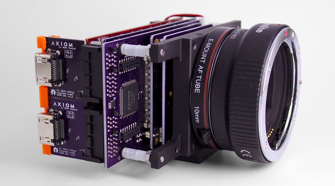
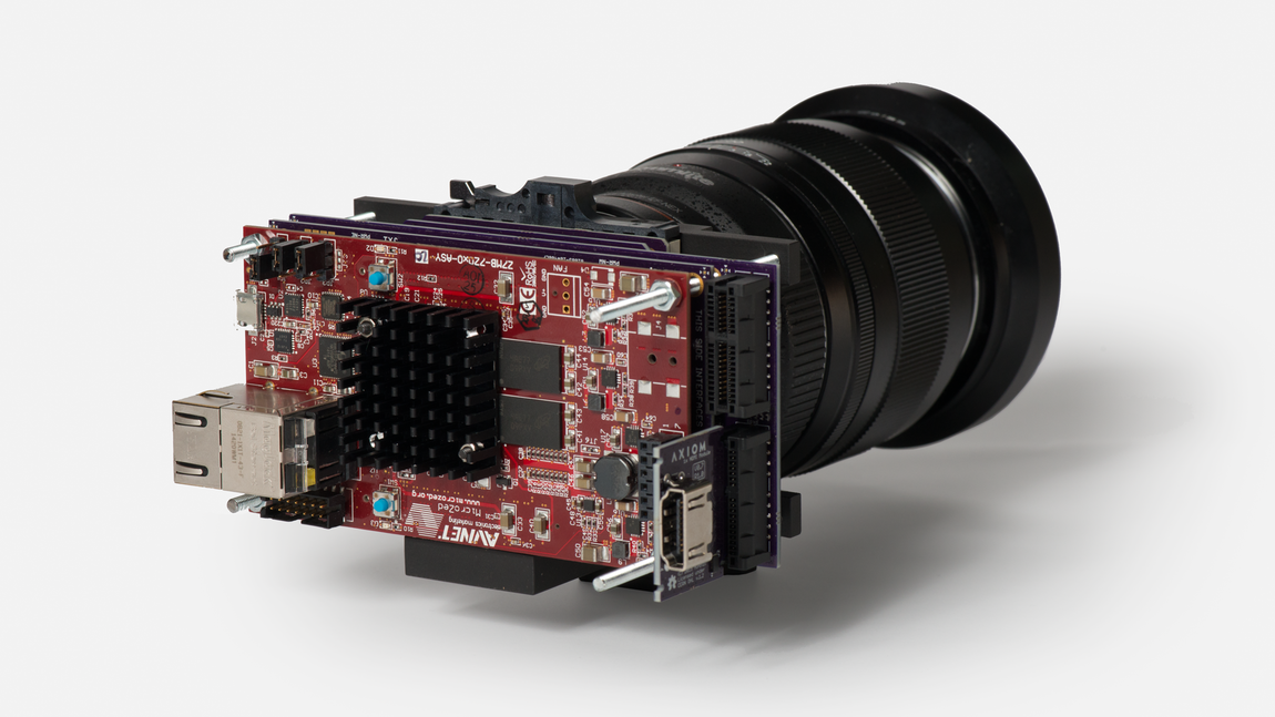
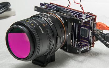
A skeleton frame provides support for the electronics, lens mount (e-mount) and tripod footplate. No surrounding enclosure allows for easy access to the AXIOM Beta's core components and their connectors.
Intended for developers and early adopters - currently shipping. See Prices.
Implications:
- Skeleton enclosure only (3D View).
- CMV12000 image sensor.
- Camera control via connected PC and Linux Terminal/Console only.
- Passive sensor cooling (works well).
- Passive E-Mount (passive Canon / Nikon adapter available).
- Screw-on UV/IR cut off filter instead of camera internal one.
- Interface Board limits image sensors throughput to 150FPS@4K (faster Interface Board replacement will be available later).
- Dual 5V 3+A AC power supply (included).
- 1x HDMI 1080p60 output module and PMOD debug module are the only plugin modules available currently (AXIOM Beta has two slots).
- Solder-on area on AXIOM Main Board not populated with gyroscopes/magnetometer/accelerator yet (will be available later on).
- Power Board requires manual reconfiguration (trimmers) when switching to a different image sensor module (potentially in the future).
- No power-on switch on camera yet (camera turns on when power is connected).
- Cameras need to be user calibrated -> Factory Calibration.
- Software/Firmware is a work in progress.
5.2.2 AXIOM Beta Compact (AB CP)
This enclosure option provides a solid but lightweight aluminum layer around the camera's electronics and incorporates several mount points and future expansion slots. Great for rig integration or general in-the-field protection. More camera control and recording options are meant to be ready together with the AXIOM Beta compact.
Note: This enclosure version is currently in development.
5.2.3 AXIOM Beta Extended (AB EX)
With the Extended enclosure the AXIOM Beta shall resemble the golden age of film cameras. With ergonomics in mind and space for an integrated recording device (AXIOM Recorder), this enclosure is intended to be ideal for shoulder mounted operation.
Note: This version of enclosure is in concept phase.
5.3 AXIOM Beta PCB Stack Layout
Version 4:
Onshape CAD workfile here
Archive:
V03.02 - File:PCB Stack Concept V03 02.pdf
5.4 Enclosures
There are several AXIOM Beta enclosure variants, some are finished and available and some are still in development. The AXIOM Beta Developer Kit (ABDK) has a skeleton framework instead of an enclosure allowing easy access to the electronics but at the same time providing a strong and solid link between hardware, lens mount and tripod mount base. This is great for developers and in lab conditions but there are several other variants that add a 3d printed, laser cut acrylic shell around this skeleton framework. There is also the Compact enclosure as very solid custom CNC milled aluminium multi part assembly.
read more: AXIOM Beta/Enclosures
5.5 Specifications
| AXIOM Beta Planned Hardware Specifications | |
|---|---|
| Image Sensor | CMV12000 (Used for research and development) |
| Lens Mount | Passive E-mount |
| Hardware Architecture | Xilinx Zynq 7020 based MicroZed |
| Modules and Shields | Single HDMI Full HD (4:4:4) output at up to 60 FPS |
| Dual 6G SDI output (in development) | |
| 3x PMOD debug module | |
| LED matrix debug module | |
| Genlock, Trigger, Timecode, LANC shields (in development) | |
| 4K Displayport/HDMI (in development) | |
| Connectivity | USB / USB UART / JTAG / Gigabit Ethernet |
| AXIOM Beta Software Features (some still in development) | |
|---|---|
| Operating System | Embedded Linux (Arch Linux) |
| Network Protocols | SSH/FTP/SCP/etc |
| Graphical User Interfaces via HTTP (in development) | |
| Capture | Global shutter Super 35 CMOS Image Sensor |
| Output | Uncompressed 4K raw (still images done, motion picture sequence currently in RGB 1060p60 max.) |
| Remote Control | Change/access all camera functions from smartphone, tablet, laptop (Web GUI (in development), Serial console, SSH) and AXIOM Remote (in development) |
| Power Management | Voltage, current, temperatures |
| Wide input voltage range (5-40V in development - currently works with 5V supply) | |
| Motion Tracking | 3D Accelerometer, 3D magnetometer and 3D gyroscope e.g. for image stabilization (in development) |
| Image Processing | Look-Up-Tables (LUTs) |
| Matrix color conversion | |
| Fixed Pattern Noise (FPN) compensation | |
| False color display | |
| Overlays | |
| Dead pixel compensation (in development) | |
| Connectivity | WiFi / Wireless adapters |
Note: As the AXIOM Beta is currently under heavy development some elements of the above table describe goals not the current state of development.
5.6 Main PCBs in Detail
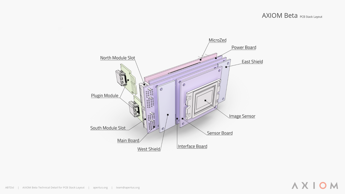
The AXIOM Beta comprises five core printed circuit boards (PCBs):
- Sensor Board
- Sensor Interface Board
- AXIOM Beta Main Board
- AXIOM Beta Power Board
- Microzed
Different plugin modules and shields can be used to add interfaces or extend functionality.
In rare cases users may want to build the camera and or its components themselves - see AXIOM_Beta/Prices for cost estimates. We can either supply all the individual components or the relevant files with a view to a user sourcing unpopulated PCBs directly from the manufacturer. In any event make contact and we'll provide guidance.
| AXIOM Beta PCB's | ||
|---|---|---|
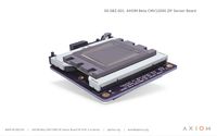
| Sensor Board | The Beta CMV12K ZIF Sensor Board hosts the heart of every cinema camera - the (CMOS) image sensor. apertus° offered three different sensor options during the crowd funding campaign; Super35, Super16 and 4/3rds, and as almost 90% of the backers opted for the Super35 sensor its respective module was developed first. The camera uses the ams Sensors Belgium CMV12000. Note: The ZIF (Zero insertion force) socket is useful for developers as it allows for the sensors removal at the turn of a lever (zero force). The AXIOM Beta Compact camera hosts the Beta CMV12K THT Sensor Board. THT (Through hole tech) is suited to applications where the sensor-front-end won't be removed regularly. | |
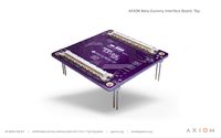
| Interface Board | The Beta Interface Dummy Board acts as a bridge between the image sensor board and the rest of the camera. It converts communication between the aforementioned components to a standard protocol so that almost any image sensor that becomes available in the future can be used with the AXIOM Beta without changing the rest of the hardware. If AXIOM users felt that 8K was in demand they would simply swap the sensor board for one capable of capturing images in the desired resolution. | |
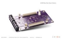
| Beta Main Board | The Beta Main Board is the equivalent of a PC's motherboard. It hosts two external medium-speed shield connectors and two high-speed plugin module slot connectors. These act as a central switch for defining where data captured by the sensor and other interfaces gets routed to inside the hardware. In this regard, all specifics can be dynamically reconfigured in software opening up a lot of new possibilities such as adding shields for audio recording, genlock, timecode, remote control protocols or integrating new codecs and image processing inside the FPGA. In the centre of the main board a 'solder-on' area has been incorporated, this will for example host chips capable of sensing the camera's orientation and acceleration (the same chips used to stabilise quadcopters and track head movements in VR headsets). Being situated directly behind the image sensor centre means that these sensors are ideally positioned to supply data for image stabilisation or metadata about the camera’s orientation and movement during a shot. | |
| CSO |
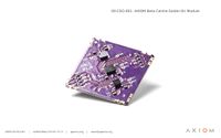
The AXIOM Beta CSO (Center Solder On) is a small addon PCB that can be added to a pre-designated area on the Beta Main Board. It hosts chips capable of measuring and controlling compensation processes via the camera's software, i.e. for orientation and acceleration (the same chips used to stabilise quadcopters and track movement in VR headsets), magnetic field related data, and three dimensional motion sensing. | |
| Beta Power Board |
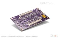
The Beta Power Board PCB generates all the different supply voltages for the chips and logic on the other PCB’s inside the camera. It also monitors currents so that it can estimate remaining power based on the recorded consumption. In the current revision of the camera a predefined set of supply voltages matching the current application with the rest of the camera have been generated, in the future however, it will be possible for users to dynamically reconfigure voltages according to their needs through the camera’s software. | |
| MicroZed |
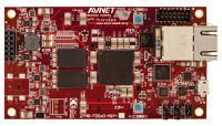
The AES-Z7MB-7Z020-SOM-G MicroZed™ is a development board based on the Xilinx Zynq®-7000 All Programmable SoC (System-on-a-Chip). It can be used as both a stand-alone development board for SoC experimentation or in a product like the AXIOM Beta. | |
5.6.1 Associated Boards
| Asoociated PCBs | ||
|---|---|---|
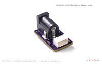
| Power Adapter Board | The Beta Power Adapter Board connects the camera to a DC power supply via pico spox cable. | |
| Power Button Board | Presently in development - The Beta Power Button Board is applicable to the AXIOM Beta Compact (ABCP) and is a simple PCB featuring an LED to signify when the camera is active. | |
5.7 Shields and Plugin Modules
The AXIOM Beta has two high speed module slots with PCIe connectors (these are not really PCIe cards, we just utilize PCIe for the connectors). Each module has a total bandwidth to/from the main processing FPGA of at least 6 Gbit/s. This makes the modules perfect for dealing with high bandwidth video outputs like HDMI/Displayport/SDI.
Due to the flexibility that this arrangement provides this could also allow us to create a dedicated solid-state media recorder module in the future. For now the AXIOM Beta relies on external recording though.
5.7.1 Shields
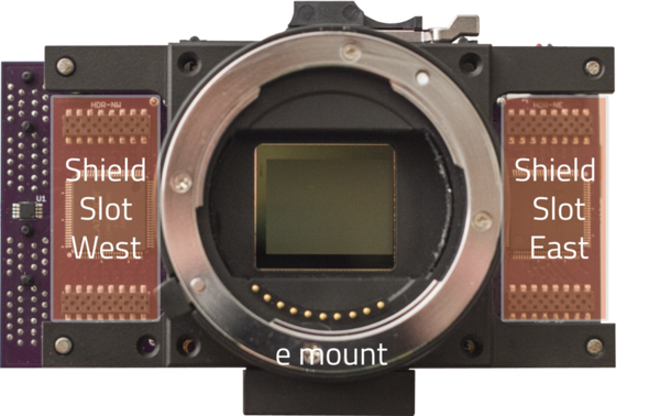
The name shields was inspired by the Arduino plugin boards that are also called "shields". AXIOM Beta sports two shield slots with space for connectors going to both sides of the camera. In contrast to modules the shields in the Beta have slow and medium speed interfaces to the main processing FPGA, and, therefore, are perfect for tasks like: trigger IN/OUT, genlock IN/OUT, timecode IN/OUT, sync IN/OUT or connecting external sensors or buttons, LCDs, etc.
The AXIOM Beta has 2 medium speed IO interfaces to be used in conjunction with "shields".
- One 200Mbit/s (west) shield interface.
- One 1Gbit/s (east) shield interface.
Note: Shields are not hot plug-able.
| AXIOM Beta Shields | ||
|---|---|---|
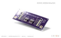
| Debug Shield | The Beta Debug Shield 2x10 GPIO banks as LED indicators plus two power LEDs. 4 LVDS pairs routed to external connectors JP1/JP2 (plus one GND). | |
5.7.2 Plugin Modules
There are 2 high speed IO interfaces where "plugin modules" can be hot plugged. They feature:
- 6.2Gbit/s each:
- 6 ✕ 950Mbit/s
- 500MBit/s GPIO
- Two modules can be combined in one 12.4 Gbit/s double height module.
- Hot pluggable.
The plugin modules are PCIe x1 connectors which are not using PCIe signaling. The bottom Plugin Module is called "south" while the top is called "north".
| AXIOM Beta Plugin Modules | ||
|---|---|---|
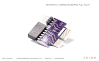
| 1x PMOD Plugin Module |
The Beta 1x PMOD Plugin Module Single PMOD debug inputs/outputs for connecting a wide range of external PMOD devices - mainly intended for development and testing when General Purpose Input/Output (GPIO) is required. | |
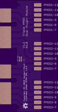
| 3x PMOD Plugin Module |
The Beta 3x PMOD Plugin Module Triple PMOD debug inputs/outputs for connecting a wide range of external PMOD devices - mainly intended for development and testing when General Purpose Input/Output (GPIO) is required. | |
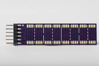
| PMOD LED Matrix Debug Module |
The PMOD LED Matrix Debug Module ... | |
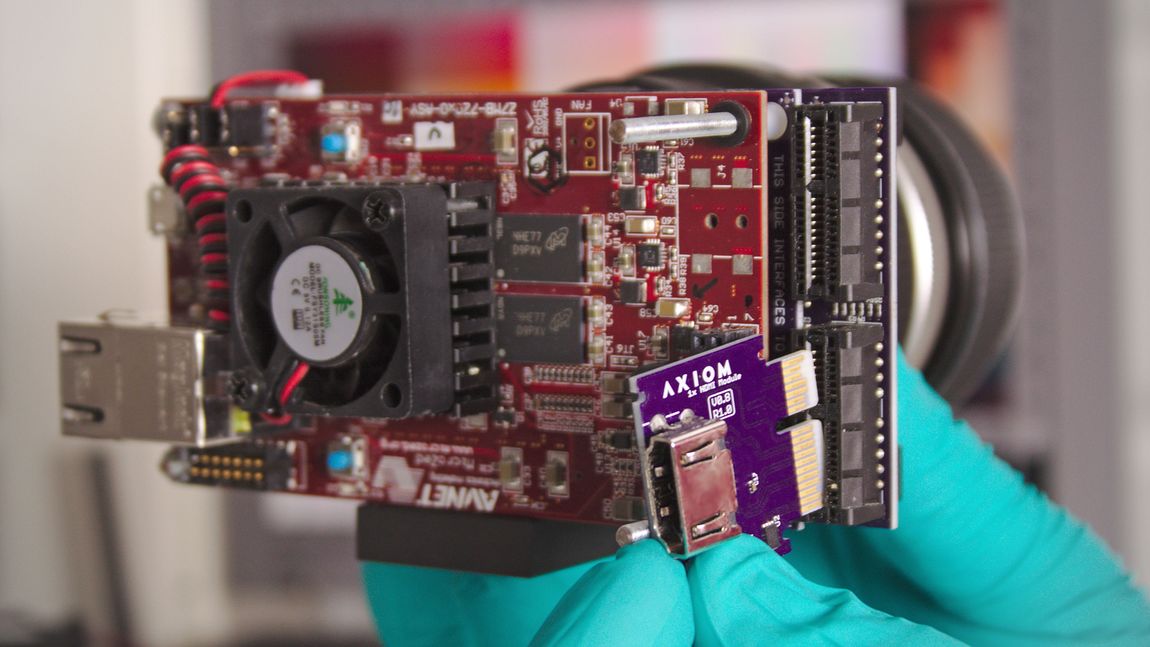
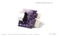
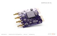
| HDMI Plugin Module | The Beta HDMI Plugin Module The 1080p60 4:4:4 output HDMI module is finished, the AXIOM Beta can accommodate up to two of these plugin modules and supply them with independent video streams. | |
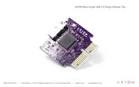
| 1x USB 3.0 Plugin Module (1x slot) | 1x USB 3.0 Plugin Module to allow storing of 4K uncompressed video to a connected PC. Offers 3.2 Gbit/s throughput which corresponds to 400MByte/s, enough to record uncompressed 4096x2160 raw 12 bit video at 25 FPS to a connected computer. | |
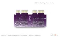
| Dual Riser Plugin Module |
The Dual Plugin Module Riser adds a 90° turn to the plugin module slots allowing them to be placed inwards on the AXIOM Beta. | |
| 4K HDMI Plugin Module |
The 4K HDMI Plugin Module Allows recording 4K/UHD video on an external recorder with a standard 2160p signal. Will also work to supply 4K/UHD screens with a signal of course. | |
| SDI Plugin Module |
The SDI Plugin Module An industry standard serial digital interface (SDI) connection plugin module will provide a nominal data transfer rate of 3G/6G. | |
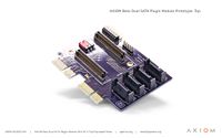
| Dual SATA Plugin Module |
The Dual SATA Plugin Module lays the foundation for the development required for writing video footage to solid state drives directly from the AXIOM Beta in the future. | |
Note: If no image or page exists in the above listings it's because the respective PCB is in development.
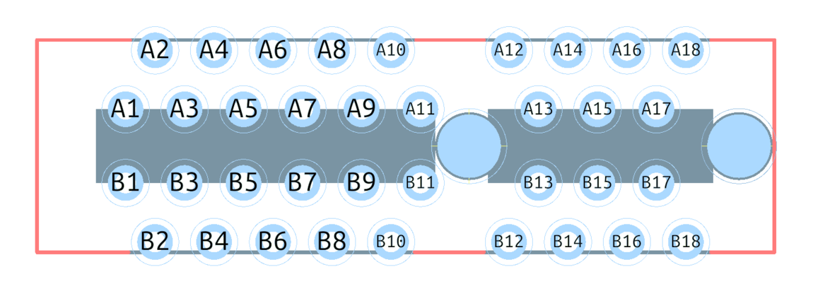
5.7.3 Plugin Module Pinout
| Pin Name | Function | Pin Name | Function |
|---|---|---|---|
| A1 | GND | B1 | I²C SDA |
| A2 | LVDS0 + | B2 | I²C SCL |
| A3 | LVDS0 - | B3 | VCC I²C (typically 3v3) |
| A4 | GND | B4 | IO 0 (typically 3v3) |
| A5 | LVDS1 + | B5 | IO 1 (typically 3v3) |
| A6 | LVDS1 - | B6 | IO 2 (typically 3v3) |
| A7 | GND | B7 | IO 3 (typically 3v3) |
| A8 | LVDS2 + | B8 | IO 4 (typically 3v3) |
| A9 | LVDS2 - | B9 | IO 5 (typically 3v3) |
| A10 | GND | B10 | IO 6 (typically 3v3) |
| A11 | Power Good; NC | B11 | IO 7 (typically 3v3) |
| A12 | GND | B12 | 5V |
| A13 | LVDS3 + | B13 | VCC (typically 3v3) |
| A14 | LVDS3 - | B14 | VCCIO LVDS (typically 2v4) |
| A15 | GND | B15 | GND |
| A16 | LVDS4 + | B16 | LVDS5 + |
| A17 | LVDS4 - | B17 | LVDS5 - |
| A18 | GND | B18 | GND |
---
---
5.8 Functions
Recording Options
The AXIOM Beta currently utilizes external third-party recorders for capturing moving images. A number of different products from different brands can record the HDMI signal from the AXIOM Beta and store the video in Prores or DNxHD. There are plans for enabling AXIOM Beta internal recording to solid state storage in the future however. In particular this is a requirement for writing high speed video as the Beta sensor is capable of capturing moving images at up to 300 FPS in full 4K resolution.
Operating System
Since the camera is running Linux, you have a full operating system at your disposal. This means any 3rd party peripherals like USB drives or wireless adapters should work out of the box. Standard protocols like SSH/FTP/SCP/etc. as well as Graphical User Interfaces via HTTP can be used to interface with the camera from computers and most mobile devices.
Sound
AXIOM Beta is not capable of recording sound internally at the moment.
How to Contribute - Growing and improving documentation is an ongoing process and you're very welcome to contribute to the project by helping to make these archives better for everyone.
