AXIOM Beta/Enclosures
There are several AXIOM Beta enclosure variants, some are finished and available and some are still in development. The AXIOM Beta Developer Kit (ABDK) has a skeleton framework instead of an enclosure allowing easy access to the electronics but at the same time providing a strong and solid link between hardware, lens mount and tripod mount base. This is great for developers and in lab conditions and there are several sub-projects that focus on adding a protective enclosure (shell) around this skeleton.
1 Skeleton Framework
The AXIOM Beta Developer kit uses the CNC milled aluminium skeleton frame and consists of the following components; Footplate, Skeleton, E-Mount lens mount and M3 threaded rods that hold the PCB Stack in place.
- See Parts: 10-Enclosures_and_Associated_Mechanical_Parts... for detailed specifications.
- Skeleton and Skeleton Footplate stl and stp files: https://github.com/apertus-open-source-cinema/beta-hardware/tree/master/Enclosure/Skeleton_E-mount
- Onshape PCB Stack and Skeleton Assembly: OnShape

1.1 Mechanical Assembly
Skeleton and Footplate are attached to each other with 2x tapered M3x12 - M3x16 screws.
Nylon spacers, washers and nuts are used on the M3 threaded rods to hold the PCBs in the correct distances.
1.2 Distance between Image Sensor and first PCB
Note: There are two versions of the Image Sensor Frontend with differing image sensor to PCB distances.
ZIF option left, THT option right:


Spacers for ZIF Version (front to back): washer, nut, 15mm spacer, washer, Main Board
M3 rod cut lengths:
- AXIOM Beta ZIF: 2x 69mm + 2x 47mm
- AXIOM Beta THT: 2x 66mm + 2x 44mm
See Parts
1.3 Dimensions
| Height | Width | Length | Weight | |
|---|---|---|---|---|
| AXIOM Beta Skeleton Frame | 65.1mm | 111.76mm | 9mm | 47.9g |
| Skeleton Footplate | 45mm | 30mm | 8mm | 27.9g |
| E-mount Lens Tube | NA | 61mm diameter | NA | 28g |
| AXIOM Beta Developer Kit (board stack, footplate, lens tube & skeleton enclosure) | 65.1mm | 111.76mm | 74mm | 319g |
2 Simple Enclosure
The Simple Enclosure provides a basic "skin" around the camera's electronics and CNC milled metal skeleton framework parts. The Simple Enclosure is designed in a way that can be produced with any consumer 3d printer. The design is not finished yet, please help finish and test it.
CAD Onshape project.
3 Transparent Enclosure
A transparent enclosure is useful for demonstrating the camera's printed circuit boards and monitoring of the camera's status LEDs. The design is made so it can be laser-cut with 3mm thick acrylic glass. Acrylic glass comes in many variations and colors and could also be used to print label text on the exterior. The acrylic sheets are designed to be installed around the camera's electronics and CNC milled metal skeleton framework parts.
Simple transparent enclosure for the AXIOM Beta, version 0.2.

Key : Black => to be cut ; Red => to be engraved ; Green => comments (not to be cut or engraved)
Open and edit the above image with Inkscape or similar.

Note: There may be scope for improvement by making the case slightly bigger (few mm wider for the front and back side), so that the HDMI cable can fit nicely in the enclosure (and you don't need to shave some plastic off the cable). If you make any alterations please update this page with modifications accordingly.
The transparent enclosure has been designed for the ZIF (CPU Socket) variant of the Sensor Frontend but should also work fine with the THT Sensor Frontend.
3.1 Heat Dissipation
Tests have shown that this transparent enclosure makes the Zynq on the Microzed prone to overheating (due to a lack of air circulation) which creates general erratic camera behaviour. Other parts in the camera can get too hot as well of course. A newer design with a larger fan on top of the enclosure has shown significant improvements in keeping the Zynq at a constant temperature.
"Case" is the above laser cut transparent enclosure
"Open" refers to the developer kit without enclosure
"Chimney" an intermediate design improvement attempt
"2xFan" a further improved design with a smaller fan on the microzed and a big fan at the top of the PCB stack
"final" the final improved design with a big fan at the top of the PCB stack but no fan on the microzed heatsink (see below)


In a closed case air flow is important and, in this case, ventilating out through holes above the fan is recommended. If you simply put a few 'holes' at the back and have a gap between a fan and the case then hot air will likely circulate inside the case, which is not what you want. Instead, it's good practice to make a 'wind-tunnel' effect, let's say.
It's also recommended to measure various temperatures on the camera and monitor them during use cases with and without case. See Temperature Sensors for more information.
The Zynq will work relatively fine up to 85°C, although that is a little high for normal use. For the sensor, you want to keep temperature quite low, typically not more than a few degrees above room temperature, so adding holes or slits close to the sensor is a good idea.
Always keep in-take holes/slits at the bottom or at least bottom side, because it aids natural convection. As a rule of the thumb, for intake you want to have about 1.5-2x the area you have for the exhaust (in total, which is the inside area of the fan). If you have too little intake, the fan gets slowed down, if you have to much, cooling will be ineffective.
4 Transparent/3D Printed Enclosure
Improved version based on the transparent enclosure (above) whereby some of the enclosure sides are 3D printed instead of being laser cut. It adds a StarTech FAN6X1TX3 60x60x10mm at top of enclosure which solves the above mentioned heat dissipation issues.
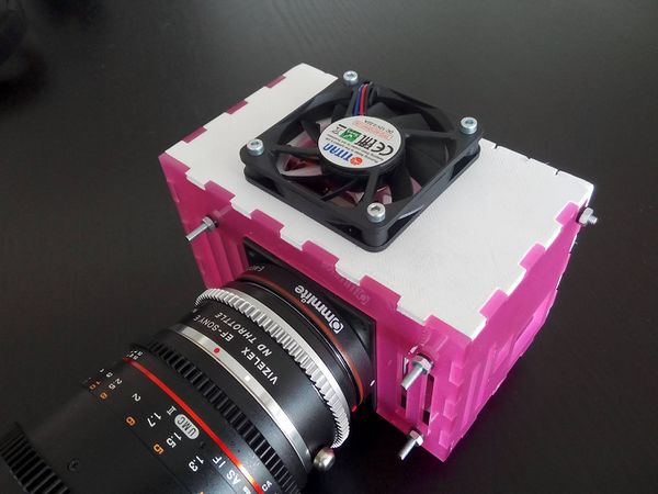
improved transparent enclosure front.
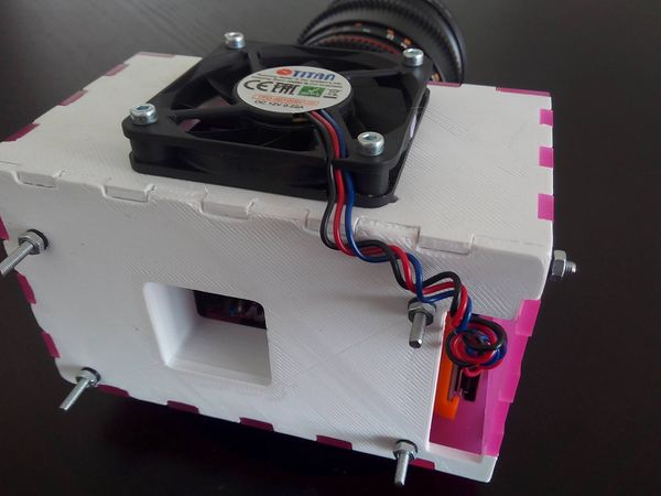
improved transparent enclosure back.


Build Instructions:
- Laser cut acrylic sheets as defined in axiombetatransparentplot.top60x60fan.svg (all plates, except the "top" and the back side).
- 3D print the 2 STL files.
- Assemble.
- Affix StarTech FAN6X1TX3 60x60x10mm cooler fan to the top plate and connect to fan connector on the Microzed .
- Each of the enclosure'opposite plates are to be held together by one or more Φ 3 mm threaded rods together with corresponding nuts (locknuts can be considered for this application - https://en.wikipedia.org/wiki/Locknut - but have not been tested yet) mounted on the exterior on each side. For the back and the front plate the rods are the same four that hold together the PCBs and the skeleton mount, albeit longer ones will be required (min 7.7 cm). For the left and right plate there the current implementation requires only one Φ 3 mm threaded rod of aprox 15 mm in length. In the current version the holes for the threaded rod in the top and bottom plate require adjustments & are misaligned, but it will be fixed in the next version (however, tests show that the enclosure holds together just fine with just the left-right & front-back rods). No shock/vibration tests have been run on it, so consider this unexplored space.
Download: File:Transparent-3d-print-enclosure.zip
5 AXIOM Beta Compact Enclosure
The AXIOM Beta Compact is an all metal enclosure for the AXIOM Beta and is CNC milled from aluminium and then anodized. Labels/logos are laser engraved.
 The design is inspired by analogue photo cameras "sandwich" design where silver elements on top and bottom sandwich a black mid section.
 Concept Rendering of the AXIOM Beta Compact Enclosure
 We manufactured two generations of prototypes in very small quantities and in 2023 had the first small batch manufactured for early adopters.
Latest designs are in this Onshape 3D CAD project.
(Onshape is a CAD design software that's entirely browser based - good for collaboration in an open source project. You can view/inspect without an account but to export/download a free account is required - paid accounts only required for private designs).
5.1 Thermal Expansion of Lens Assembly
According to https://goodcalculators.com/thermal-expansion-calculator/ and an aluminium lens mount assembly with a distance from sensor to bayonet of 19.4mm, the thermal expansion of 25°C temperature difference is 0.01mm, so can be considered negligible.
5.2 E-mount FFD verification
The defined flange focal distance (FFD) between image sensor plane and lens bayonet for e-mount is 18mm. Though glass elements in the optical path affect that distance as they have a higher density as the air the light is envisioned to pass through in that 18mm (https://www.spektrum.de/lexikon/optik/planflaechenabbildung/2588).
AXIOM Beta Compact Enclosure Optical Path (cross section):

Distance Notes:
- Spring ring under bayonet: 0.3mm thickness
- Sensor CMOS surface to outer front plate surface: Version 1: 6.75mm / Version 2: 4.75mm + 0.244mm (delta from cover glass)
- every filter holder thickness should be 2mm + own filters delta (the assembly always requires two filter holders in place for the correct FFD)
- shimming should account for 0.15mm in the FFD
5.3 Cooling and Airflow
At the top of the AXIOM Beta Compact enclosure in the "Cap Top" part and it integrates a 12V 60x60x10mm fan. By using a relatively large fan we can spin it slower meaning more silent operation. The fan pushes hot air out at the top. The air enters the enclosure at the bottom ventilation holes and flows through the electronics. As heat rises this natural motion is supported by the fan.

There is a thin layer of PVC with fine hole grid pattern as filter.
Image sensor cooling is done with a custom two part heat sink attached to the back of the image sensor with a silicon rubber thermal pad and pushed onto the image sensor back with 2 spring screws. The heat sink elements are anodized as according to https://www.gabrian.com/anodized-aluminum-heatsinks-what-you-need-to-know/ this increases the surface emissivity.
5.4 Filter Holders
The default stack contains two optical filter holders:
- 1x UV/IR cut off filter
- 1x empty (to provide space for adding a second filter later on)
Each filter holder features two orientation pins to prevent being inserted in a wrong orientation. These orientation pins also act as shim holder.
Each filter holders thickness is 2mm by default plus the FFD delta as a result of the optical filter holders own filter thickness/density. So in reality an optical filter holder will be something like 2.15 or 2.34mm thick depending on the glass element it holds.
The filter holder incorporates a rubber gasket ring with 1.5mm thickness and 58mm outer diameter, 55mm inner diameter corresponding to a ring length of 177.5mm. (eg. https://www.ebay.com/itm/10x-Metric-Nitrile-Rubber-NBR-O-Ring-Seals-Washers-Cross-Section-1-5mm-OD-5-80mm/173895045434) This gasket seals the holder towards the image sensor side.
5.4.1 UV/IR cut off filter
The visible spectrum that humans can see ranges from 380 - 750 nm.
Currently we are shipping Dev Kits with Haida Pro II MC Digital Slim UV / IR 390nm / 750nm filters.
Hoya filters offer a narrower band of 390 nm - 700 nm - will need to be tested how it impacts less red tones.
http://www.optics-online.com/IRC.asp?PN=IRC30-50x50 50x50mm for 39$ for sample (volume pricing likely lower and on request), 1.5mm thickness
UQG Optics offer 40x40x1.1mm UV/IR Cut off filters with 400 - 690nm bandpass
5.5 Thread Inserts
We decided to use thread inserts for all external attachment points (1/4" and 3/8") instead of cutting threads into the aluminum directly. This is a bit more expensive but the threads are stronger, easier to replace in case any of them wear or get damaged over time so its better for repair-ability. We opted for steel helicoils as thread inserts.
5.6 AXIOM Shell
features this cold shoe.
5.7 Extended Plugin Module Cartridge
Plugin Modules can be any length, for this concept a flexible way to enclose the PCB is required. The following concept is a 2 part assembly:

To make space for the cartridge walls plugin module PCBs that shall fit into this extended cartridge need to be a bit less high (max: 26.575mm).

Further requirements for the PCB so it will fit inside this cartridge enclosure:
- component height on bottom side is limited to 3mm
- component height on top side is limited to 7.5mm
Example of a 60mm long cartridge installed in CP enclosure top slot and HDMI (normal length) Plugin Module installed in bottom slot.:

6 Legacy
Switchable ND Filters not planned currently