Difference between revisions of "00-Printed Circuit Boards"
| Line 111: | Line 111: | ||
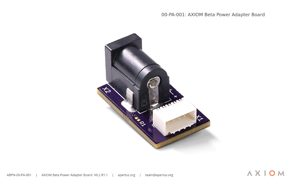
==:00-PA: AXIOM Beta Power Adapter Board== | |||
[[File:00-PA-001- AXIOM Beta Power Adapter Board V0.2R1.1 Show sm.png | 1150px |]] | |||
[https://wiki.apertus.org/images/9/9c/00-PA-001-_AXIOM_Beta_Power_Adapter_Board_V0.2R1.1_Show.png Full size image.] | |||
BOMs and Schematics of all AXIOM Beta Power Adapter Boards- https://wiki.apertus.org/index.php/Beta_Power_Adapter_Board | |||
---- | ---- | ||
Revision as of 19:16, 8 March 2019
1 00-SB: Sensor Boards
The Beta CMV12K ZIF Sensor Board hosts the heart of every cinema camera - the (CMOS) image sensor. apertus° offered three different sensor options during the crowd funding campaign; Super35, Super16 and 4/3rds, and as almost 90% of the backers opted for the Super35 sensor its respective module was developed first. The camera uses the ams Sensors Belgium CMV12000.
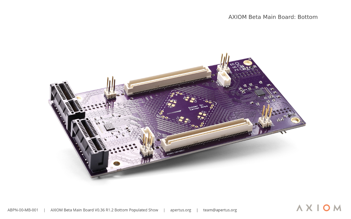
2 00-MB: Main Boards
The Beta Main Board is the camera's equivalent of a PC's motherboard. It hosts two external medium-speed shield connectors and two high-speed plugin module slot connectors - These act as a central switch for defining where the data that's captured by the sensor and other interfaces gets routed to inside the hardware. In this regard, all specifics can be dynamically reconfigured in software.
BOMs and Schematics of all AXIOM Beta Main Boards - https://wiki.apertus.org/index.php/Beta_Main_Board
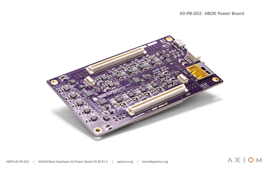
3 00-PB: Power Boards
The AXIOM Beta Power Board PCB generates all the different supply voltages for the chips and logic on the other PCB’s inside the camera. It also monitors currents so that it can estimate remaining power based on the recorded consumption. In the current revision of the camera a predefined set of supply voltages matching the current application with the rest of the camera have been generated, in the future however, it will be possible for users to dynamically reconfigure voltages according to their needs through the camera’s software.
BOMs and Schematics of all AXIOM Beta Power Boards - https://wiki.apertus.org/index.php/Beta_Power_Board
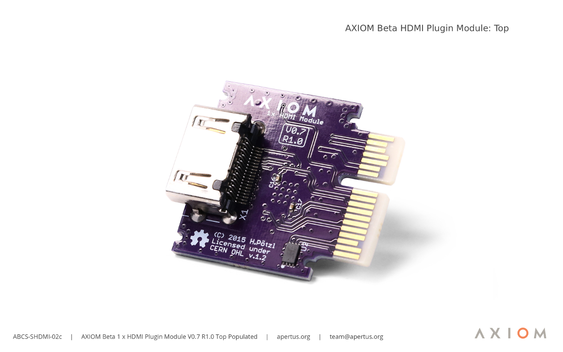
4 00-SHDMI: HDMI Plugin Modules
This module provides one 1080p60 HDMI output stream via 4 LVDS channels directly from the Zynq on the Microzed.
BOMs and Schematics of all AXIOM Beta HDMI Plugin Modules - https://wiki.apertus.org/index.php/Beta_HDMI_Plugin_Module
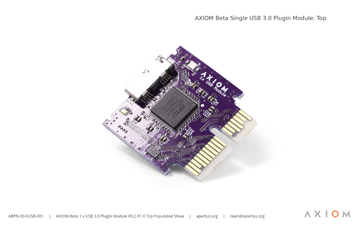
5 00-SUSB: USB 3.0 Plugin Modules
With the USB 3.0 plugin module, any computer with USB 3.0 connectivity can be used as an AXIOM Recorder. This allow for defining format/container/metadata/etc. of uncompressed raw 4k footage.
BOMs and Schematics of all AXIOM Beta HDMI Plugin Modules - https://wiki.apertus.org/index.php/1x_USB_3.0_Plugin_Module
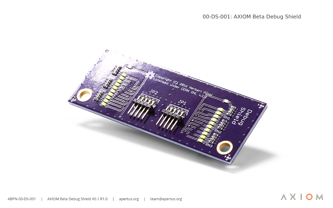
6 00-DS: AXIOM Beta Debug Shields
The AXIOM Beta has 2 medium speed IO interfaces to be used with "shields".
BOMs and Schematics of all AXIOM Beta Debug Shields - https://wiki.apertus.org/index.php/Beta_Debug_Shield
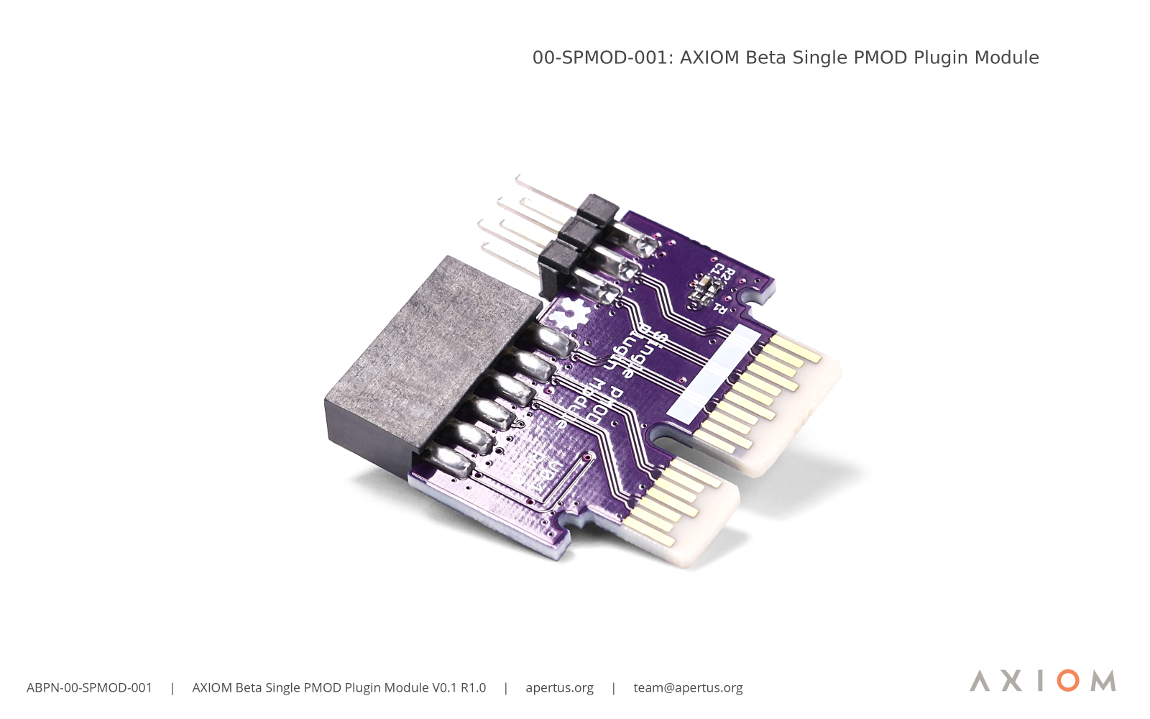
7 00-SPMOD: AXIOM Beta Single PMOD Plugin Module
The Beta 1x PMOD Plugin Module features PMOD debug inputs/outputs for connecting a wide range of external PMOD devices - mainly intended for development and testing when general purpose Input/Output (GPIO) is required.
BOMs and Schematics of all AXIOM Beta Single PMOD Plugin Modules- https://wiki.apertus.org/index.php/Beta_1x_PMOD_Plugin_Module
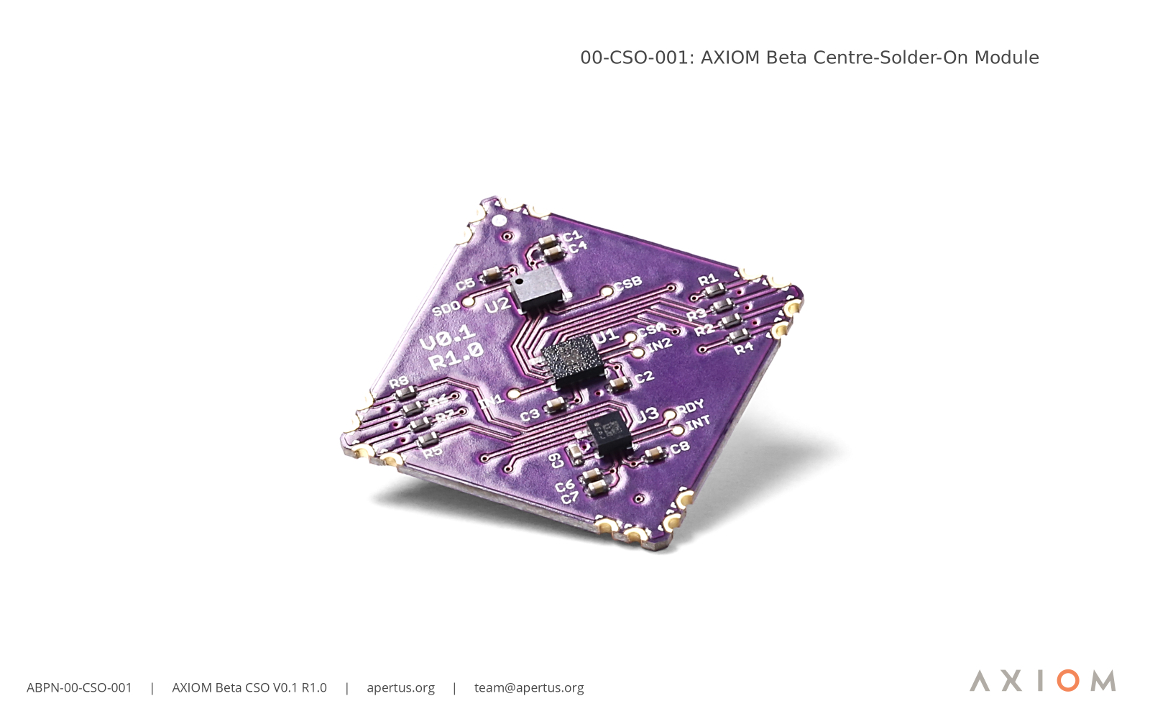
8 00-CSO: AXIOM Beta Centre-Solder-On Module
Some of the floor space in the centre of the AXIOM Beta Main Board has been left clear so that a CSO (centre-solder-on) board can be incorporated. This will host chips capable of measuring and controlling compensation processes via the camera's software, i.e. for orientation and acceleration (the same chips used to stabilise quadcopters and track movement in VR headsets), magnetic field related data, and three dimensional motion sensing.
BOMs and Schematics of all AXIOM Beta CSOs- https://wiki.apertus.org/index.php/Beta_CSO
9 :00-PA: AXIOM Beta Power Adapter Board
BOMs and Schematics of all AXIOM Beta Power Adapter Boards- https://wiki.apertus.org/index.php/Beta_Power_Adapter_Board
- 00-SB-002-0V16-1R3c
- 00-SB-003-1V2-1R2
- 00-SiB-001-0V12-1R0
- 00-TPMOD-001-1V2-1R0
- 00-TPMOD-002-1V2-1R1
- 00-PMODD-001-1V0


